Vision-based highway overhead structure detection system

a technology of overhead structure and detection system, applied in the field of detection system, can solve the problems of not only detecting moving and stationary vehicles, radar sensor limitation, and existing vehicle system challenges to overcome, so as to reduce the number of false alarms, effectively warn users, and eliminate the effect of false alarms

Inactive Publication Date: 2006-04-11
HRL LAB
View PDF11 Cites 71 Cited by
  • Summary
  • Abstract
  • Description
  • Claims
  • Application Information

AI Technical Summary

Benefits of technology

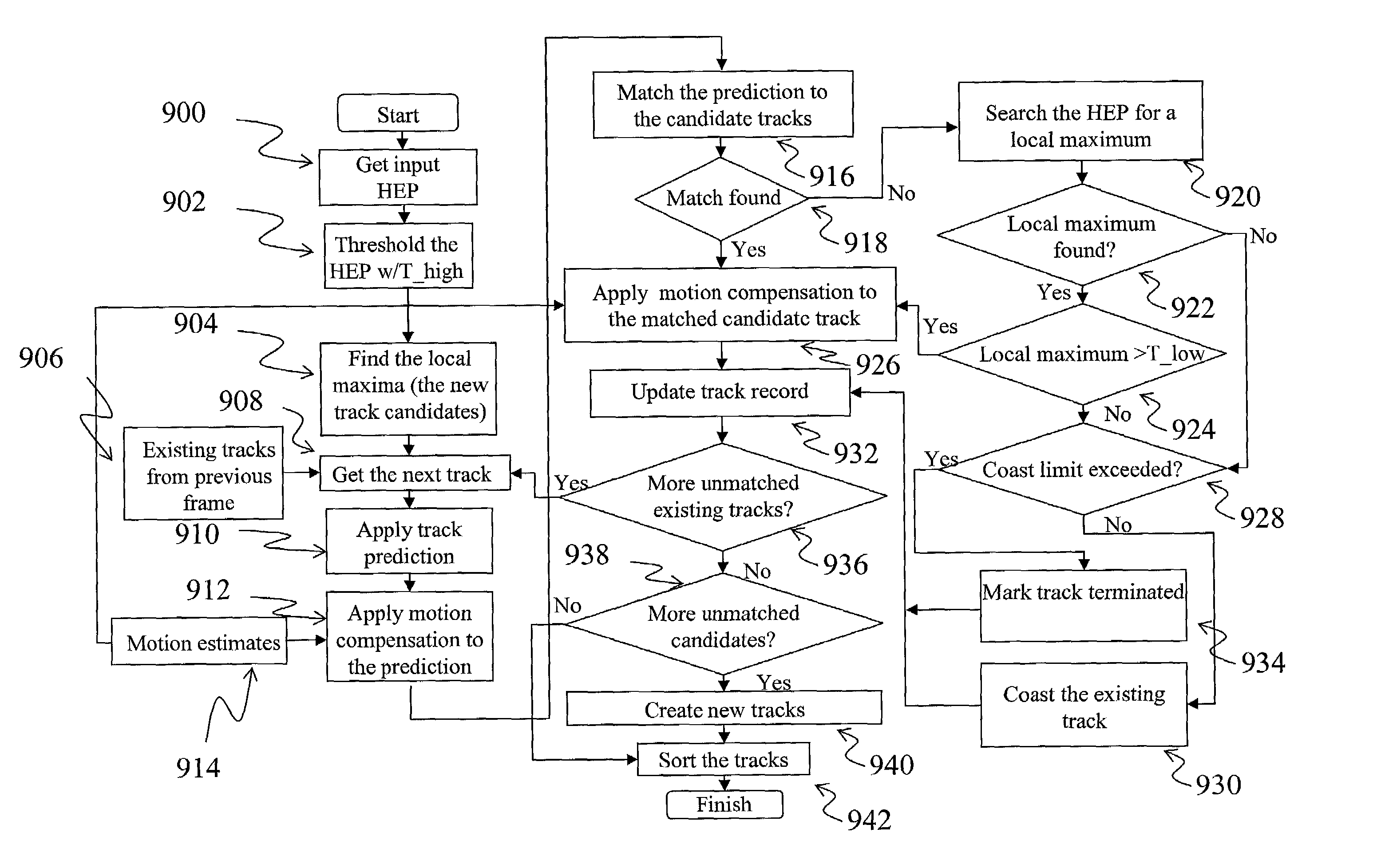
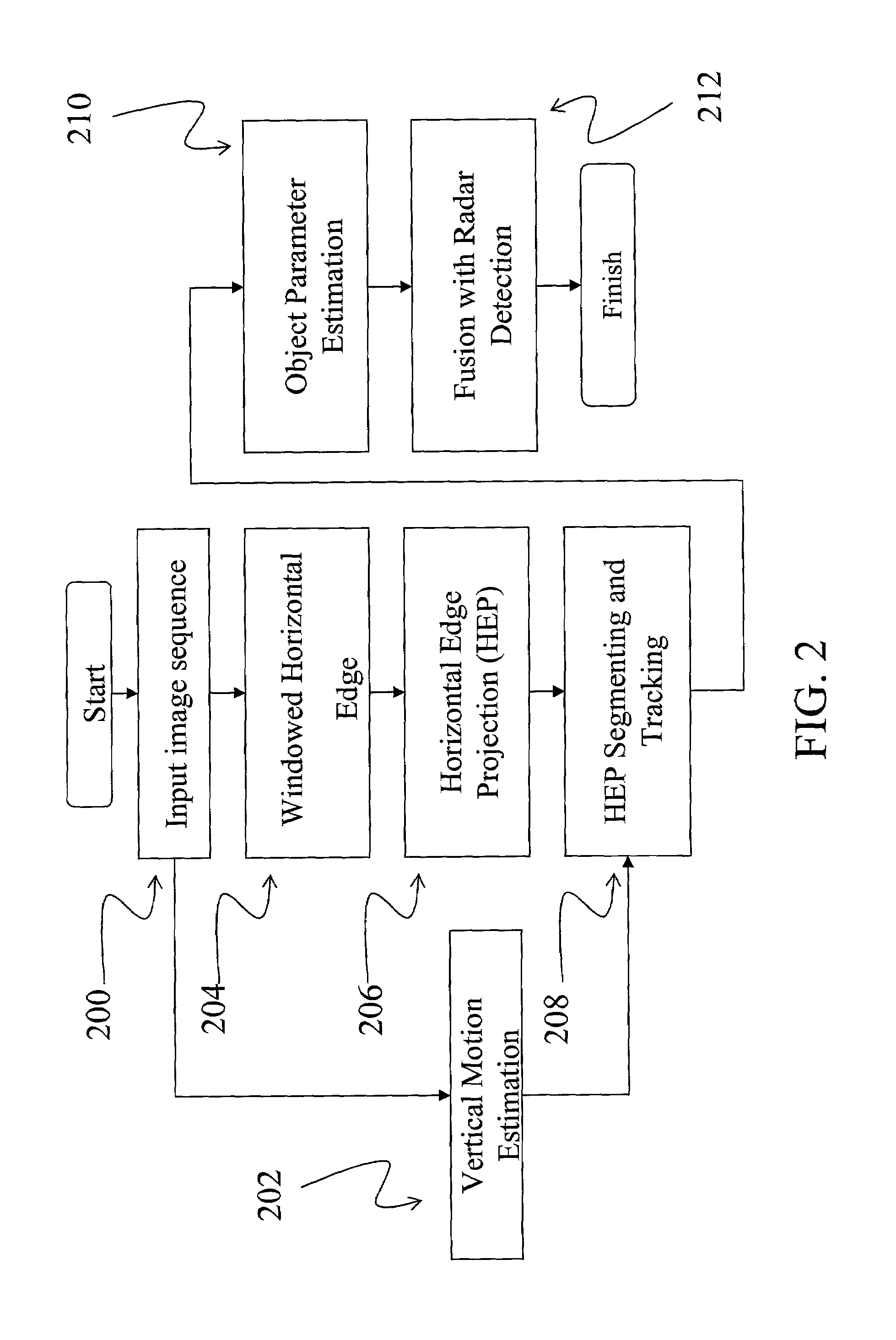
[0005]The present invention provides a robust method and apparatus that effectively warns users when there is a potential for collision and simultaneously minimizes or eliminates the number of false alarms. The embodiments described herein relate to a vision based identification system that can be used for the reduction of false radar sensor alarms, preferably due to overhead objects. The identification system utilizes an image collection device mounted in a vehicle to supply an image processor with images of objects ahead of the vehicle. The image processor analyzes the images and extracts horizontal edges from each frame. These edges are then tracked through successive image frames by taking into account both the vertical and the forward motion of the vehicle. The distance and height of the horizontal edges from the vehicle are determined and tracked. The tracked horizontal edges are subsequently supplied to a radar sensor processor. When the data from the image processor is matched with the data from the radar sensor processor, false alarms that would be generated by these overhead objects can be avoided.
[0006]One embodiment of the invention includes an apparatus and method for reducing the incidence of vehicle collisions. The embodiment provides an image capture device, such as a video camera, an image processor, a radar transceiver, and a radar signal processor. In this embodiment the image capture device is configured to provide a video signal to the image signal processor. The radar transceiver is configured to provide input to the radar signal processor, and the image processor and radar signal processor are configured to provide input to a matching processor where the combined processed signals complement each other and allow the apparatus to effectively identify elements likely to result in false radar sensor alarms. By squelching the rate of false alarms, the effectiveness of vehicle collision avoidance systems is enhanced.
[0008]In another embodiment of the invention, wherein the tracking of horizontal edge projection vectors is assisted by using one or both of the following, vertical motion compensation or forward motion compensation. The vertical motion compensation helps predict where the tracked horizontal edge projection vectors will be located on successive image inputs by compensating for vertical motion. Similarly forward motion compensation helps predict where tracked horizontal edge projection vectors will be located on successive image inputs by compensating for forward motion. The forward motion compensation can be achieved by using a plurality of previous points from one or more previous images.

Problems solved by technology

While the autonomous vehicle will probably exist at some time, existing vehicle systems still have many challenges to overcome in order to be practical.
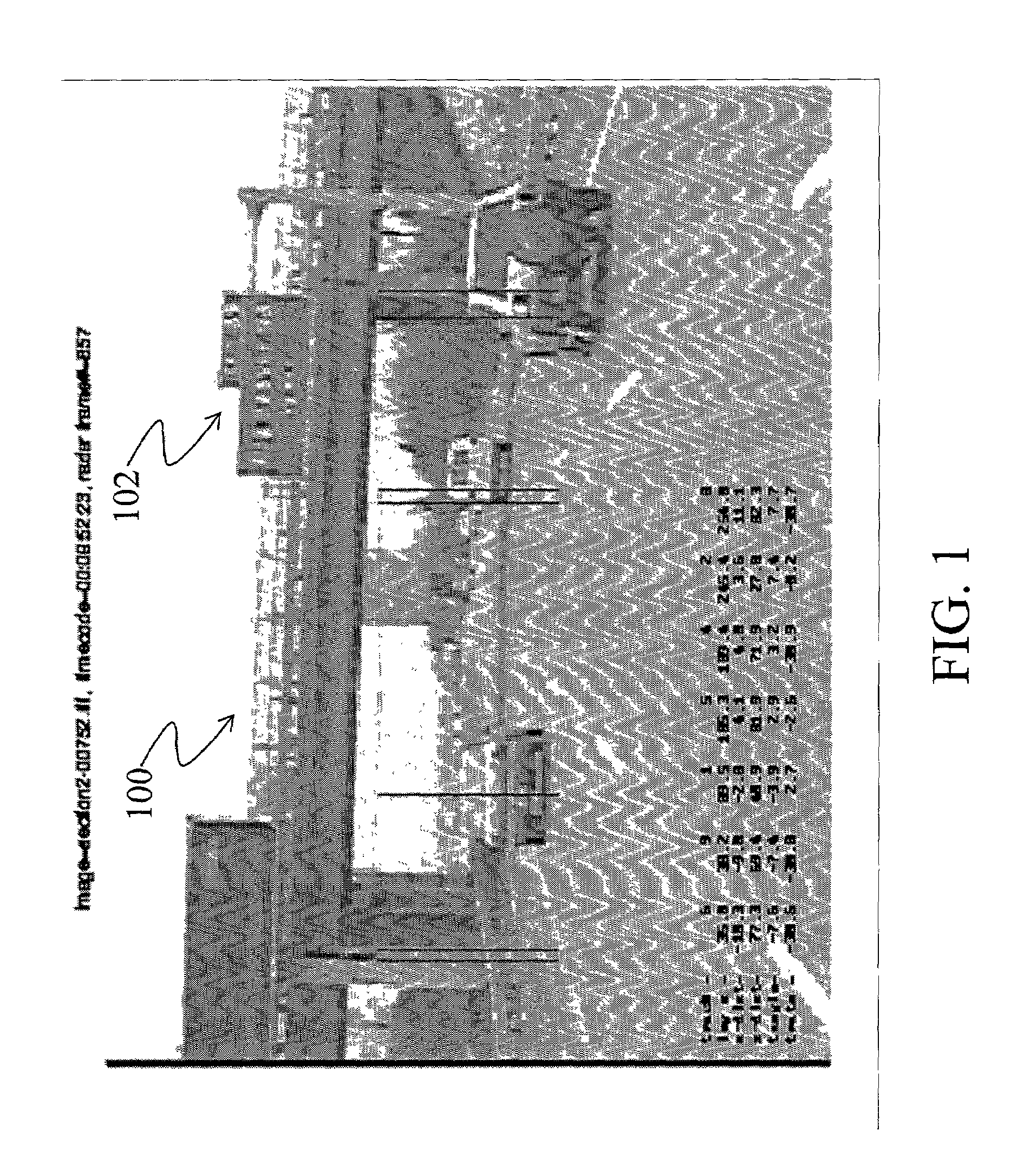
The radar sensor has a limitation in that it not only detects moving and stationary vehicles, but also many fixed roadway infrastructures, such as overpasses and overhead signs.
There are a number of possible explanations for the false alarms, including, misalignment of the radar axis relative to the ground, often as a result of the radar transmitter being aimed too high.
Additional possible sources of error include radar side lobes, and certain types of terrain.
The terrain based error sources can occur because overhead objects may actually be within the vertical field of view due to the slope of the road.
Therefore redesigning a radar sensor to provide a narrower vertical beam will not likely be successful in solving the problem completely.
Additionally, many of these solutions could result in a less robust system that might miss actual obstructions and may still generate false alarms.

Method used


Image

  • Vision-based highway overhead structure detection system
  • Vision-based highway overhead structure detection system
  • Vision-based highway overhead structure detection system

Examples


Embodiment Construction

[0023]The present invention provides a method and apparatus for reducing the false alarm rate associated with vehicle collision warning systems. The invention augments radar-based collision warning systems, and is configured to reduce the false alarm rate associated with conventional systems' misidentification of overhead objects as collision threats. The following description, taken in conjunction with the referenced drawings, is presented to enable one of ordinary skill in the art to make and use the invention and to incorporate it in the context of particular applications. Various modifications, as well as a variety of uses in different applications, will be readily apparent to those skilled in the art, and the general principles defined herein may be applied to a wide range of embodiments. Thus, the present invention is not intended to be limited to the embodiments presented, but is to be accorded the widest scope consistent with the principles and novel features disclosed herei...


PUM


Abstract

An image sequence is inputted 200 from the camera and vertical motion is estimated 202. A windowed horizontal edge projection 204 is extracted from the inputted image sequence 200 and the horizontal edges are projected 206. The horizontal edge projection 206 and the vertical motion estimation 202 are combined in a horizontal segmentation and tracking element 208, and forwarded to an object parameter estimation element 210 where the object's distance and height are estimated. This data is combined in a fusion with radar detection element 212. By correctly matching the overhead objects sensed by the radar and video camera, the proximity and relative speed can be ascertained. Once overhead objects have been identified they can be isolated and not considered for collision avoidance purposes.

Description

TECHNICAL FIELD[0001]This invention relates generally to a detection system and more specifically to an apparatus and method for detecting objects in a motor vehicle environment.BACKGROUND OF THE INVENTION[0002]There has been notable progress in the development of fully autonomous automobiles capable of navigating through traffic without human intervention. For example, systems may use sensing technology to warn drivers of impending collisions, or even take control of a vehicle in certain situations where the driver either ignores or cannot heed a warning. While the autonomous vehicle will probably exist at some time, existing vehicle systems still have many challenges to overcome in order to be practical.[0003]Some collision warning systems use a radar-based detector, combined with a vision-based land-sensing module, to detect and track vehicles ahead of the host vehicle. The radar-based system monitors the moving pattern of all objects tracked by the radar sensor to determine pote...

Claims


Application Information

Patent Timeline
Patent Type & Authority Patents(United States)
IPC IPC(8): G06K9/00G08G1/04G08G1/16
CPCG01S13/867G08G1/04G08G1/164G01S13/931B60T2201/08B60T2201/089
Inventor CHEN, YANG
Owner HRL LAB
Why Eureka
Try Eureka