Monitoring system
a monitoring system and image processing technology, applied in the field of image processing technique, can solve the problems of reducing the channel capacity of the transmission path, and the storage capacity of the buffer memory needed for the image processing section, so as to reduce the amount of image data to be transmitted, and sacrifice the quality of the synthesized image
- Summary
- Abstract
- Description
- Claims
- Application Information
AI Technical Summary
Benefits of technology
Problems solved by technology
Method used
Image

Examples
embodiment 1
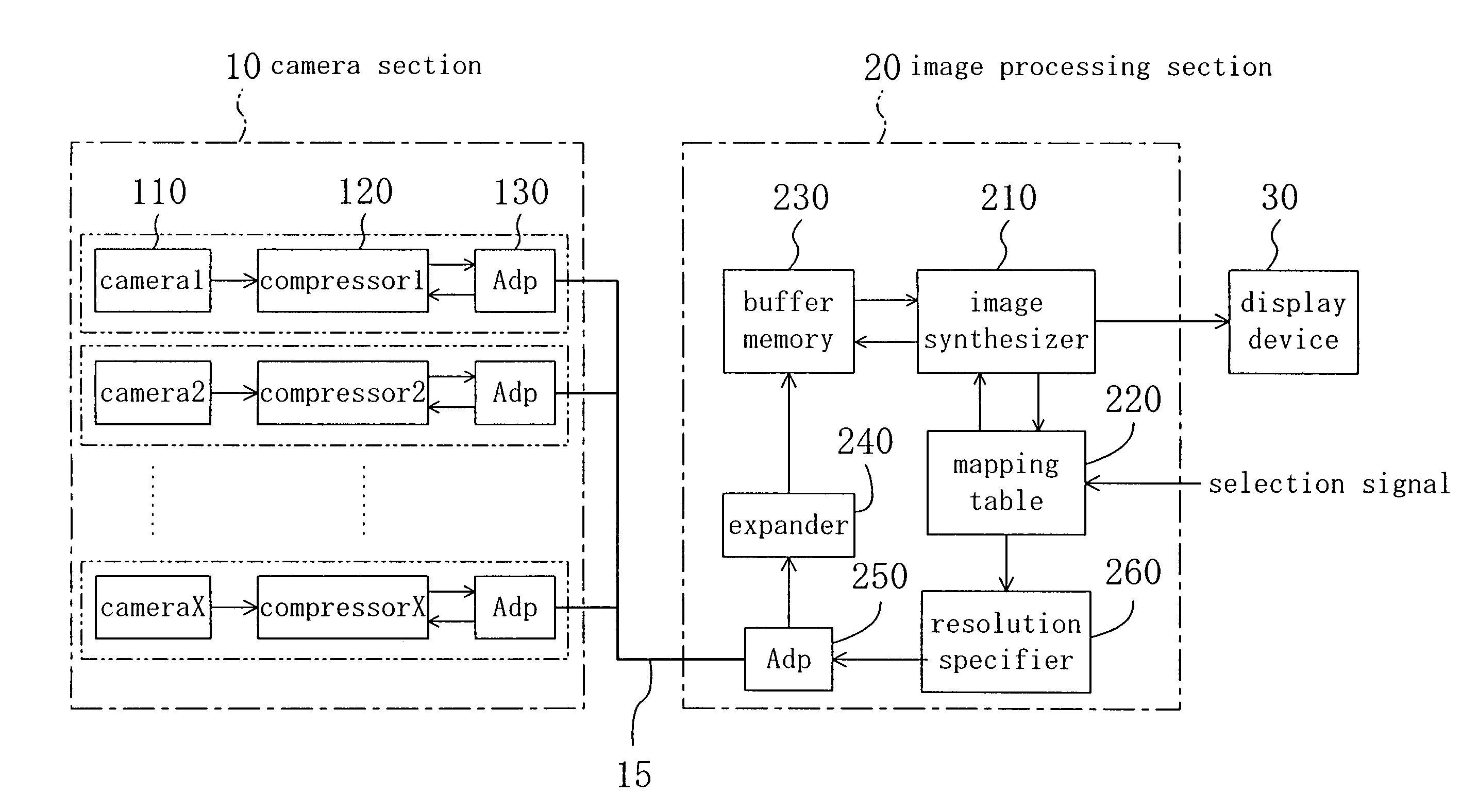
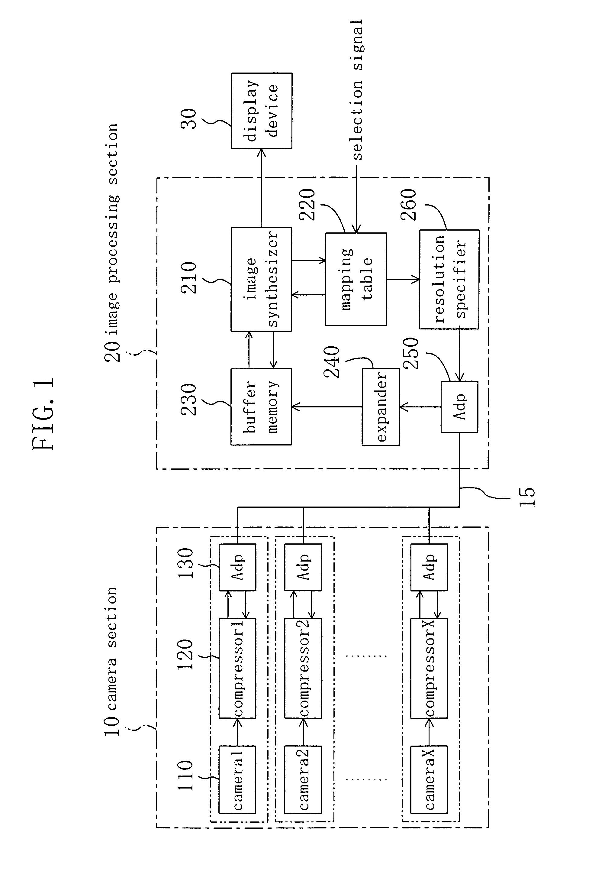
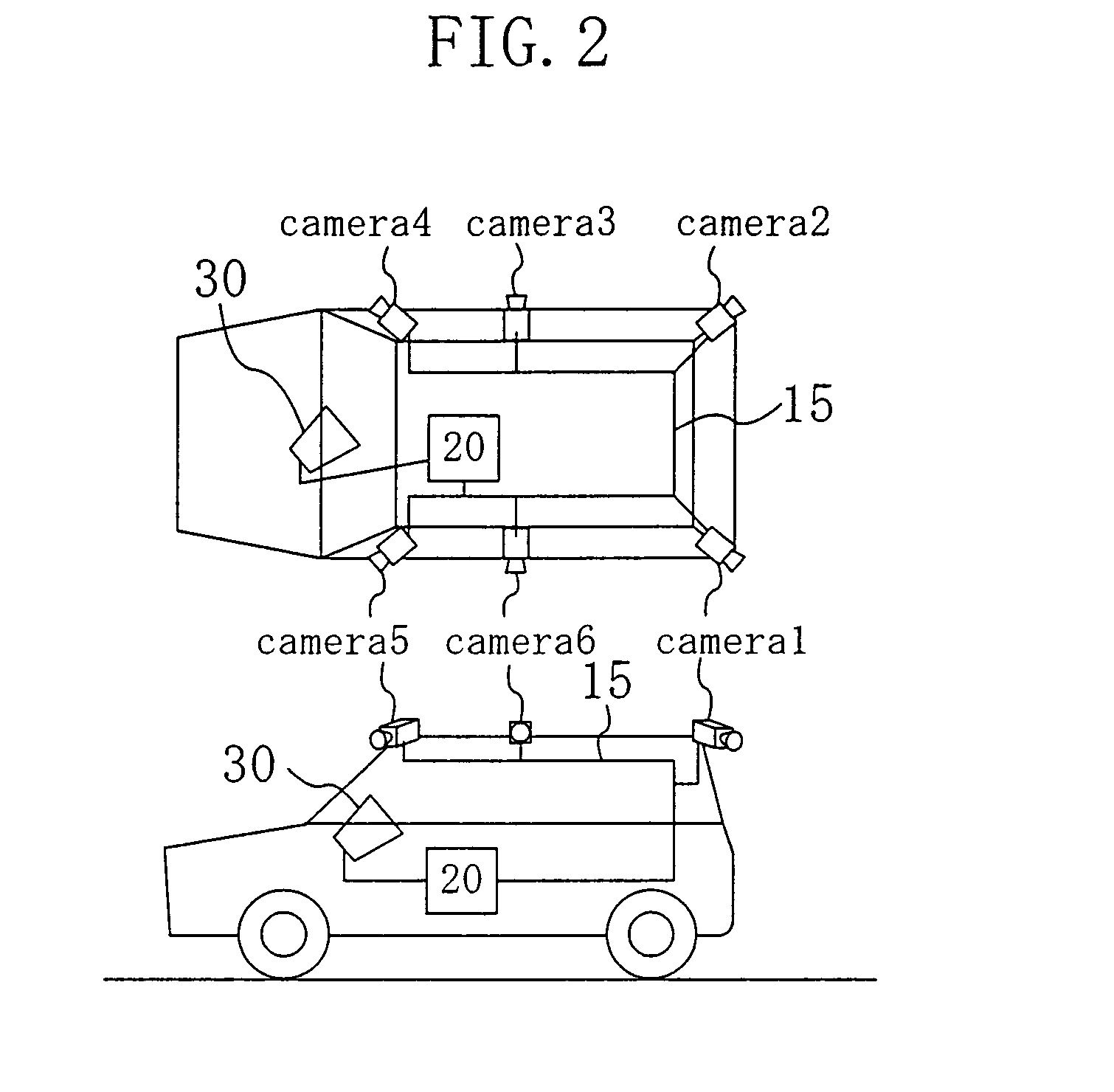
[0041]FIG. 1 is a block diagram illustrating a configuration for a monitoring system according to a first embodiment of the present invention. The monitoring system shown in FIG. 1 is supposed to be mounted on a vehicle and used as an aid for vehicle driving operations (e.g., parking). Specifically, this system combines together images that have been taken by multiple cameras mounted on a vehicle to produce a synthesized image, which looks as if the vehicle were captured by a camera located over the vehicle, for example. Then, the system presents the virtual image to the driver. By looking at the synthesized image presented, the driver can know an exact positional relationship between his or her own vehicle and its surroundings, and can park his or her vehicle much more safely, for example.
[0042]As shown in FIG. 1, the monitoring system includes camera section 10, transmission line 15, image processing section 20 and display device 30. The camera section 10 includes a number X of ca...
embodiment 2
[0098]FIG. 12 is a block diagram illustrating a configuration for a monitoring system according to a second embodiment of the present invention. The monitoring system shown in FIG. 12 is basically the same as the counterpart shown in FIG. 1. In FIG. 12, each component also shown in FIG. 1 is identified by the same reference numeral and the detailed description thereof will be omitted herein.
[0099]The system shown in FIG. 12 is different from the counterpart shown in FIG. 1 in that the image processing section 20A of the system shown in FIG. 12 further includes readout controller 270 and sync signal generator 280. In response to the output of the resolution specifier 260, the readout controller 270 generates a readout control signal for each camera 110A. The sync signal generator 280 generates a sync signal for each camera 110A. The readout control and sync signals, output from the readout controller 270 and sync signal generator 280, respectively, are transmitted from the transmissi...
embodiment 3
[0117]FIG. 15 is a block diagram illustrating a configuration for a monitoring system according to a third embodiment of the present invention. The monitoring system shown in FIG. 15 has basically the same configuration as the counterpart of the first embodiment shown in FIG. 1.
[0118]The third embodiment of the present invention is different from the first embodiment in that the system of the third embodiment cuts down the amount of each camera image by removing the image data of an area that should be unnecessary for image synthesis, not by compressing the image data. For that purpose, the image processing section 20B of the third embodiment includes an area specifier 290 as alternative cutdown mode selecting means instead of the resolution specifier 260. The area specifier 290 specifies the area that should be necessary for image synthesis for each camera image. Also, the camera section 10B of the third embodiment does not include the compressors 120 but selectors 140. Each of the...
PUM
 Abstract
Description
Claims
Application Information
 - R&D
- Intellectual Property
- Life Sciences
- Materials
- Tech Scout
- Unparalleled Data Quality
- Higher Quality Content
- 60% Fewer Hallucinations
Browse by: Latest US Patents, China's latest patents, Technical Efficacy Thesaurus, Application Domain, Technology Topic, Popular Technical Reports.
© 2025 PatSnap. All rights reserved.Legal|Privacy policy|Modern Slavery Act Transparency Statement|Sitemap|About US| Contact US: help@patsnap.com