Structural member and a method of manufacturing said member

a technology of structural members and manufacturing methods, applied in the field of structural members, can solve the problems of relatively high cost and difficult handling of flexible tubes, and achieve the effects of reducing thickness, facilitating the manufacture of members, and improving the retention of inner leg sections

Inactive Publication Date: 2006-04-18
MDT VMORTEN DAHL
View PDF32 Cites 6 Cited by
  • Summary
  • Abstract
  • Description
  • Claims
  • Application Information

AI Technical Summary

Benefits of technology

[0010]By forming the U-shaped structural member of a corrugated material and by the provision of the double-walled leg portions, the structural member is flexible so that it may conform to the surface to which it is to be fastened, but is after fastening to the surface resistant to ending, torsional tensile and compressive forces and creates a good base for placement of load-carrying composite material, primarily on the base portion. The corrugated structure makes it possible to use a material having a substantially reduced thickness in relation to other elements having corresponding properties with respect to rigidity and strength, thus providing a lightweight product.
[0011]In a preferred embodiment, the corrugations of e

Problems solved by technology

However, the flexible tube is relativ

Method used


Image

  • Structural member and a method of manufacturing said member
  • Structural member and a method of manufacturing said member
  • Structural member and a method of manufacturing said member

Examples


Embodiment Construction

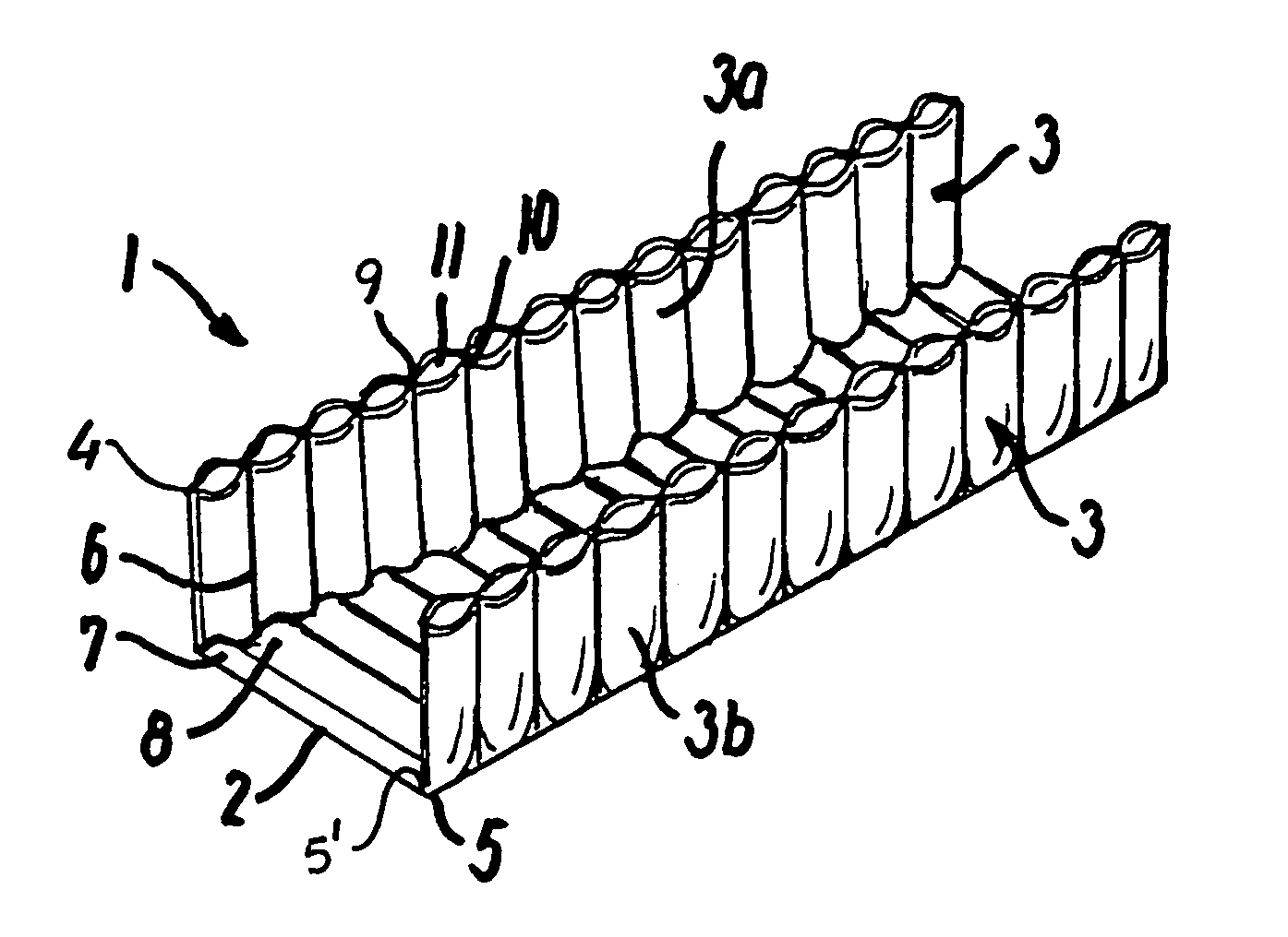
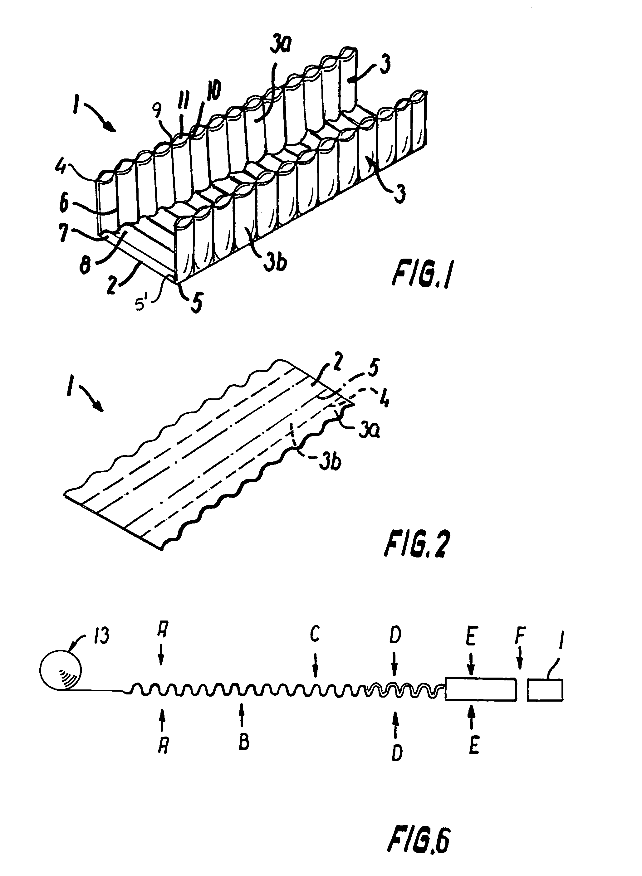
[0026]The generally U-shaped structural member 1 as shown in FIG. 1 comprises a base portion 2 and two leg portions 3 extending at substantially right angles from the base portion 2. Each leg portion 3 is double-walled and comprises a first section 3a which forms the inner wall and a second section 3b which forms the outer wall of the leg portion 3.

[0027]The structural member 1 is formed integrally from at least one sheet or foil of any suitable plastic or metal material, or a combination thereof. The thickness of the sheet or foil lies in the range of 0.01 to 0.5 mm, an example being an aluminum foil having a thickness of 0.1 mm. The material of the sheet or foil depends on the intended field of use of the structural member. In applications, in which the thermal properties such as thermal conductivity is desirable a metal sheet or foil material is preferred. Furthermore, two or more foils or sheets, possibly of different materials, may be positioned on top of each other in order to...


PUM

PropertyMeasurementUnit
Thicknessaaaaaaaaaa
Lengthaaaaaaaaaa
Thicknessaaaaaaaaaa

Abstract

The structural member (1) has a generally U-shaped cross-section and comprises a base portion (2) and two leg portions (3) extending at substantially right angles from said base portion. The member comprises at least one thin sheet or foil which is corrugated in a continuous waveform in the longitudinal direction of the member. Each leg portion (3) includes a first section (3a) forming an inner wall of the leg portion and a second section (3b) parallel with said first section and joining the first section along a first joining line (4) and the base portion along a second joining line (5). The structural member according to the invention is flexible so that it may conform to the surface to which it is to be fastened, but is after fastening to the surface resistant to bending, torsional, tensile and compressive forces and creates a good base for placement of load-carrying composite material, primarily on the base portion. The corrugated structure makes it possible to use a material having a substantially reduced thickness in relation to other elements having corresponding properties with respect to rigidity and strength. The structural member is intended to be connected with a structure to be reinforced or in order to provide eg. heating or ventilation.

Description

BACKGROUND OF THE INVENTION[0001]1. Technical Field of the Invention[0002]The present invention relates to a structural member having a generally U-shaped cross-section and a longitudinally extending configuration, comprising a base portion and two leg portions extending at substantially right angles from said base portion.[0003]Such structural members are used in a wide field of applications, and their structure and material vary according to the demands made by the particular field.[0004]2. Prior Art[0005]For instance, international published application No. WO 90 / 03921 discloses a support member for pallets, comprising a channel having a generally U-shaped cross-section. The support member is manufactured from flat sheets of metal, such as steel or aluminum. In order to increase the stiffness of the support member, ribs are pressed into the base and side panels at regular intervals along the length of the support member. The support member disclosed in this document presents good...

Claims


Application Information

Patent Timeline
IPC IPC(8): E04B9/00E04F13/04E04C3/04E04C3/07E04C3/28
CPCE04C3/07E04C3/28E04C2003/0413Y10T428/24149E04C2003/0439E04C2003/0473Y10T29/49616E04C2003/043
Inventor DAHL, MORTEN
Owner MDT VMORTEN DAHL
Why Eureka
Try Eureka