Macrolaminate radial injector

a radial injector and radial injector technology, applied in the direction of engine starters, engine/propulsion engine ignition, lighting and heating apparatus, etc., can solve the problems of high rejection or scrap rate and labor-intensive process, and achieve good spray patternization, reduce nox and co emissions, and good dispersion

Active Publication Date: 2006-04-18
PARKER INTANGIBLES LLC
View PDF27 Cites 70 Cited by
  • Summary
  • Abstract
  • Description
  • Claims
  • Application Information

AI Technical Summary

Benefits of technology

[0012]The present invention provides a novel and unique fuel injector having a cylindrical configuration and a plurality of compact and lightweight nozzles that provide sprays of fine droplets of fuel, and includes integral structure that allows the introduction of air or other fluid into or in conjunction with the fuel. According to one application of the invention, the injector is useful for gas turbine applications and includes a feed ring with a plurality of nozzles spaced around the circumference of the ring, where each nozzle has a low Flow Number, and an integral air swirler that reduces NOX and CO emissions. The nozzles provide good spray patternization and the fuel spray is well dispersed for efficient combustion. In addition, the nozzles can be accurately and repeatably manufactured.
[0013]According to the present invention, the feed ring of the injector includes a plurality of thin, flat T-shaped plates of etchable material disposed in adjacent, surface-to-surface contact with one another. A plurality of nozzles are formed in a linear, evenly-spaced array along the head nozzle portion (transversely extending arms) of the plates. Each nozzle includes a metering assembly formed in one or more of the plates to provide a fine spray of fuel; and an integral swirler structure formed in one or more of the plates. The swirler structure allows the introduction of air or other fluid into or in conjunction with the fuel spray.
[0019]Injectors constructed according to the present invention have a cylindrical configuration that is lightweight and compact, and can be used to introduce a second fluid into a fuel spray. In gas turbine applications, the injector can be used to introduce a swirling air flow into a fuel spray to enhance mixing and reduce NOX and CO emissions from the gas turbine engine. The swirling flow also enhances flame stability by generating toroidal recirculation zones that bring combustion products back towards the fuel injection apparatus thereby resulting in a sustained combustion and a stable flame. The swirling flow also provides good spray patternization and the fuel spray is well-dispersed for efficient combustion.

Problems solved by technology

It is believed that for many years it was only possible to manufacture many of the openings and surfaces of small nozzles to create such low Flow Numbers by using relatively low volume machine tool and hand tool operations in connection with high magnification and examination techniques.
This was a labor-intensive process with a high rejection or scrap rate.

Method used


Image

  • Macrolaminate radial injector
  • Macrolaminate radial injector
  • Macrolaminate radial injector

Examples


Embodiment Construction

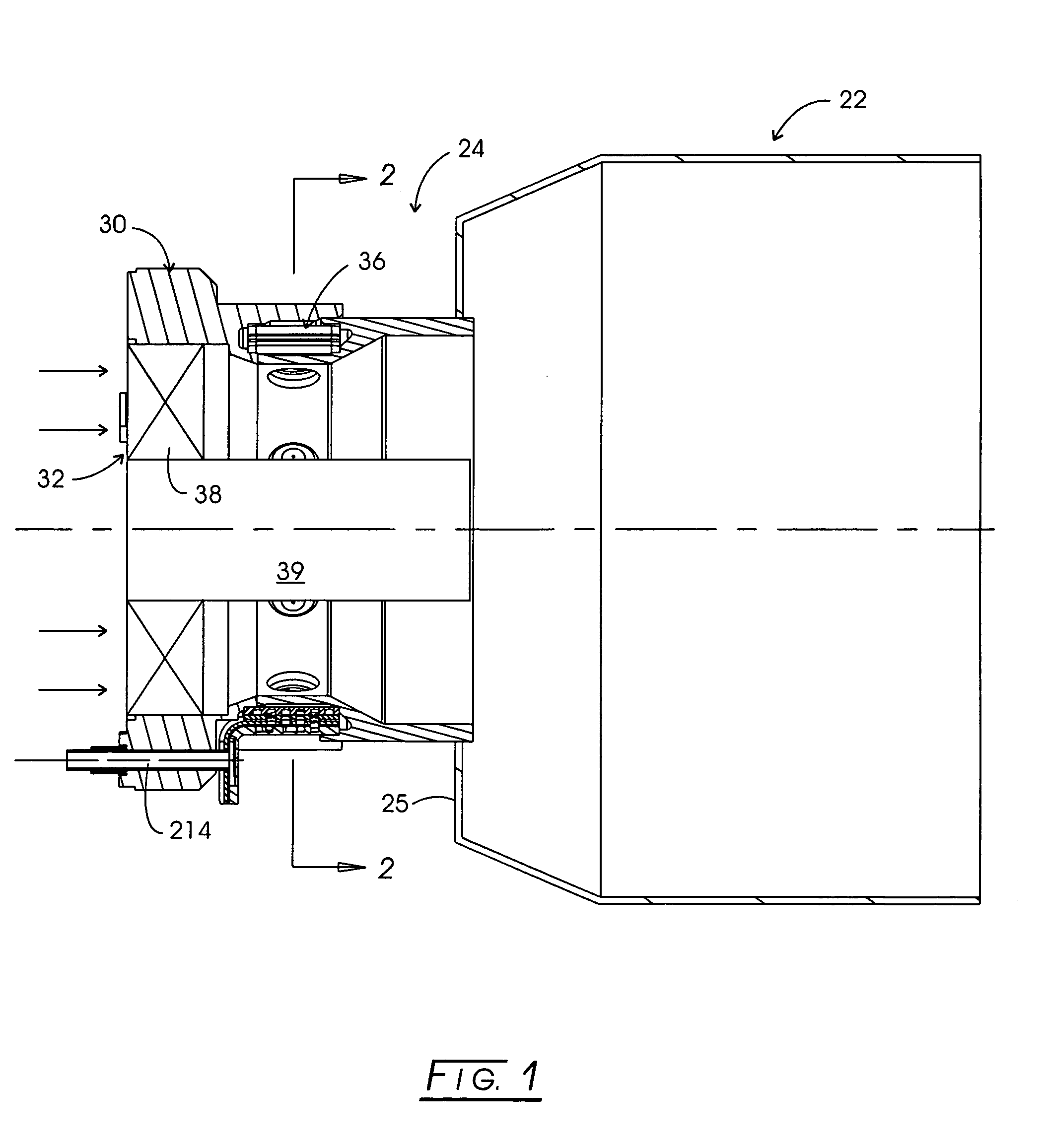
[0038]Referring to the drawings and initially to FIG. 1, a portion of a combustion system for a turbine engine is indicated generally at 20. The system includes a combustion chamber 22; and a fuel injector assembly, indicated generally at 24, mounted to the upstream end wall 25 of the combustion chamber. The fuel injector assembly 24 atomizes and directs fuel into the combustion chamber 22 for burning, as should be well known to those skilled in the art. Combustion chamber 22 can be any useful type of combustion chamber, such as a combustion chamber for industrial power generation equipment; however, the present invention is believed useful for combustion chambers for other types of combustion applications, such as in ground vehicles, where a fine dispersion of fuel droplets of two fluids (e.g., a liquid fuel and air) is desirable. One particularly useful application for the combustion system of the present invention is in the premixer described in U.S. Pat. No. 6,311,473, owned by ...


PUM


Abstract

An injector assembly includes a barrel-shaped housing and an injector, the injector including a feed ring formed of multiple, etched, T-shaped plates. A plurality of nozzles are arranged in an evenly-spaced array around the injector and direct fluid radially inward into the central annulus of the injector assembly. The injector includes an air inlet port with an internal feed passage fluidly connected to swirl chambers and exit orifices to provide individual sprays of fuel from the nozzles. Integral air swirlers impart a swirling component of motion to the fuel sprays. A venturi configuration is provided by the housing. The nozzles are provided along the venturi configuration, which maintains fluid separation from the walls of the housing downstream from the venturi.

Description

CROSS-REFERENCE TO RELATED CASES[0001]The present application claims the benefit of the filing date of U.S. Provisional Application Ser. No. 60 / 487,092; filed Jul. 14, 2003 and U.S. Provisional Ser. No. 60 / 498,626; filed Aug. 28, 2003, the disclosures of which are expressly incorporated herein by reference.FIELD OF THE INVENTION[0002]This invention relates in general to injectors for dispensing fluids in fine sprays, and more particularly relates to fuel injectors for dispensing liquid fuel in fine sprays for ignition in gas turbine engines.DESCRIPTION OF THE PRIOR ART[0003]The art of producing sprays of liquid is extensive. Many injectors have a nozzle with a swirl chamber. One or more angled inlet slots direct the fluid to be sprayed into the swirl chamber. The inlet slots cause the fluid to create a vortex in the swirl chamber adjacent to a spray orifice. The fluid then exits through the spray orifice in a conical spray. Patents showing such injectors include U.S. Pat. Nos. 4,613...

Claims


Application Information

Patent Timeline
Patent Type & Authority Patents(United States)
IPC IPC(8): F23R3/28F02C7/22
CPCF02C7/22F23R3/28F23R2900/00018
Inventor MANSOUR, ADEL B.ODAR, ANDREW M.STEINTHORSSON, ERLENDUR
Owner PARKER INTANGIBLES LLC
Why Eureka
Try Eureka