Sensor having resin mold casing and method of manufacturing the same

a technology of resin mold and sensor, which is applied in the direction of optical radiation measurement, simultaneous indication of multiple variables, instruments, etc., can solve the problems of increasing reducing the degree of freedom in the design and specification of the sensor, and increasing the response and/or sensitivity of the sensor, so as to prevent moisture, reduce the manufacturing cost of the sensor, and improve the response and/or sensitivity.

Inactive Publication Date: 2006-04-18
DENSO CORP
View PDF10 Cites 19 Cited by
  • Summary
  • Abstract
  • Description
  • Claims
  • Application Information

AI Technical Summary

Benefits of technology

[0017]In the sensor manufactured by the above method, the predetermined part of the sensor casing is exposed outside from the connector casing. Therefore, the sensing portion detects the physical quantity through this part of the sensor casing, so that the response and / or the sensitivity of the sensor can be improved. Further, no potting material as a sealing is necessitated for sealing between the sensor casing and the connector casing, so that a manufacturing cost of the sensor is limited to increase.
[0018]Preferably, both the first and second resins are thermoplastic resin. Therefore, both thermoplastic resins are molded together by heat in a secondary mold process so that no clearance is formed between the sensor casing and the connector casing. Thus, this construction can prevent moisture from penetrating into the sensor.
[0019]Preferably, physical properties of the first resin are different from those of the second resin, and the first resin provides high fluidity, and the second resin provides high mechanical strength.

Problems solved by technology

Therefore, it is difficult to increase the response of the sensor and / or the sensitivity of the sensor, so that the degree of freedom in design and specification of the sensor becomes lower.
Moreover, a potting material as a sealing is necessitated for sealing between the molded IC 1 and the casing 2, so that a manufacturing cost of the sensor is increased.

Method used


Image

  • Sensor having resin mold casing and method of manufacturing the same
  • Sensor having resin mold casing and method of manufacturing the same
  • Sensor having resin mold casing and method of manufacturing the same

Examples


Embodiment Construction

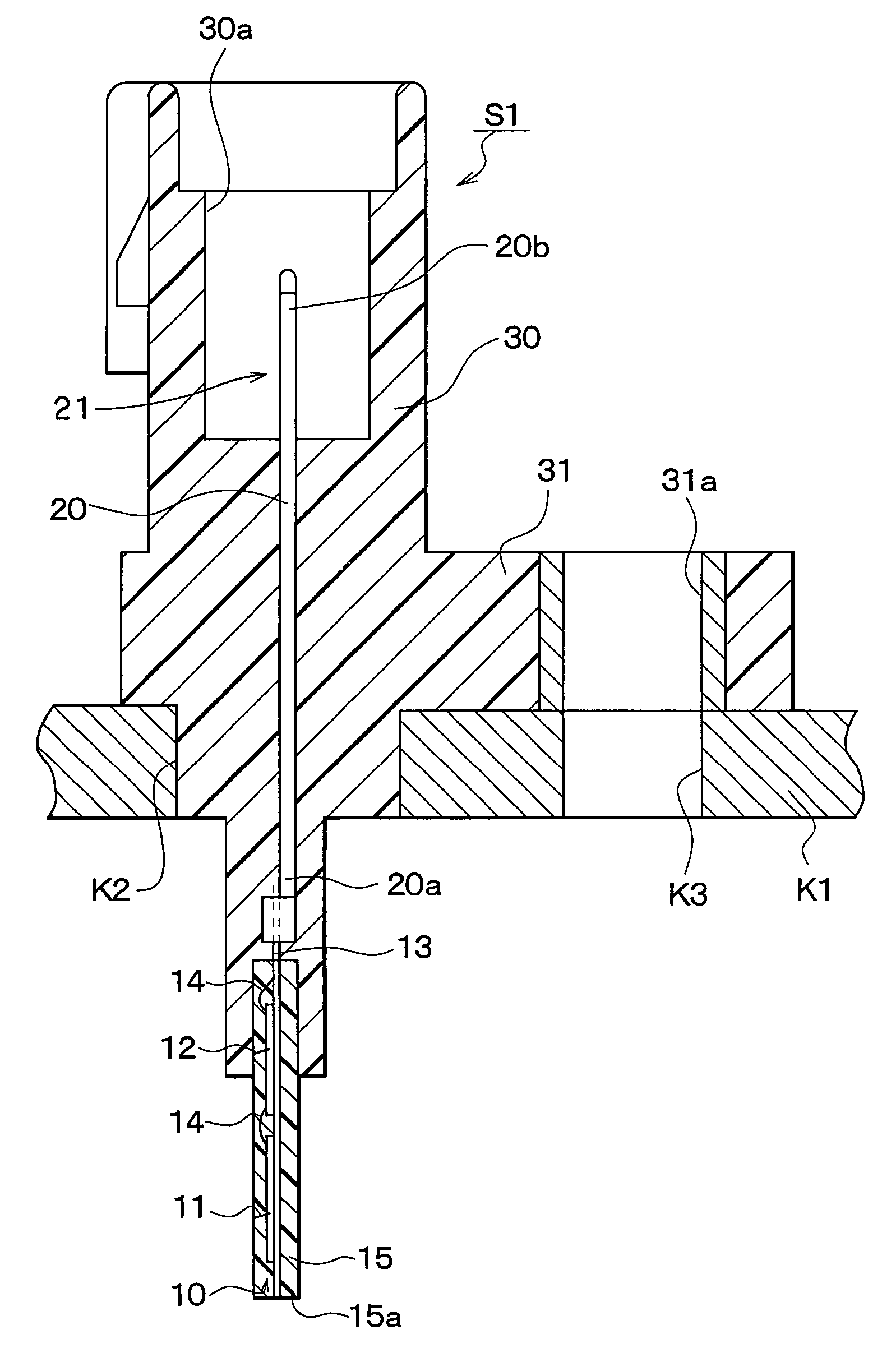
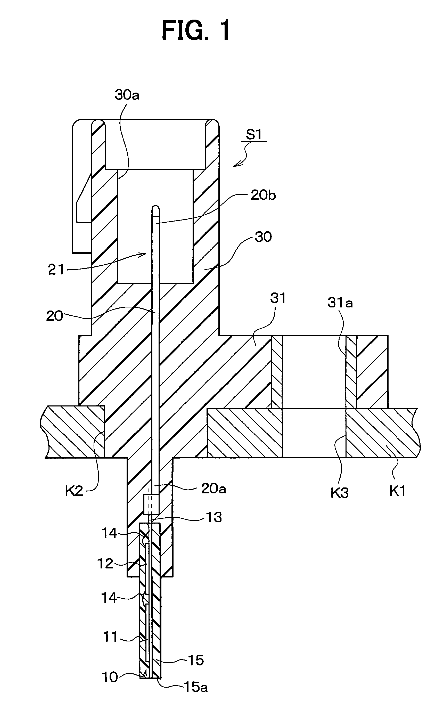
[0023]A sensor S1 according to a preferred embodiment of the present invention is shown in FIG. 1. The sensor S1 senses a physical quantity such as temperature, magnetic field, acceleration and angular velocity.

[0024]The sensor S1 is mounted in an attachment K1 so that the sensor S1 senses temperature or magnetic field through the attachment K1, or acceleration or angular velocity applied to the attachment K1. The sensor S1 includes a sensing portion 10 and a connector portion 21. The sensing portion 10 includes a sensing element 11 for sensing the physical quantity and for outputting a sensor signal according to the sensed physical quantity, and an electric circuit 12 for processing the sensor signal from the sensing element 11.

[0025]The sensing element 11 is, for example, a thermistor in case of a temperature sensor, a magneto-resistance device in case of a magnetic sensor, or a sensor having a movable portion in case of an acceleration sensor and an angular velocity sensor. Here,...


PUM

PropertyMeasurementUnit
physical propertiesaaaaaaaaaa
fluidityaaaaaaaaaa
mechanical strengthaaaaaaaaaa

Abstract

A sensor includes a sensing portion for sensing physical quantity, a connector portion integrated with the sensing portion for electrically connecting the sensing portion and an outer circuit outside the sensor, a sensor casing for accommodating the sensing portion, and a connector casing for accommodating the connector portion. Both the sensor casing and the connector casing are made of thermoplastic resin. The sensor casing has a predetermined portion exposed outside from the connector casing. The other portion of the sensor casing is covered with the connector casing.

Description

CROSS REFERENCE TO RELATED APPLICATION[0001]This application is based on Japanese Patent Application No. 2002-366794 filed on Dec. 18, 2002, the disclosure of which is incorporated herein by reference.FIELD OF THE INVENTION[0002]The present invention relates to a sensor having a resin mold casing and a method of manufacturing the same. Specifically the resin mold casing accommodates a sensing portion and a connector portion, which are made of resin, respectively.BACKGROUND OF THE INVENTION[0003]A sensor having a resin mold casing according to a prior art is shown in FIG. 2. The sensor is disclosed in U.S. Pat. No. 6,034,421. The sensor includes a molded IC 1 having an IC chip as a sensing element and a casing 2 having a connector portion. The molded IC 1 is primarily molded with thermosetting resin such as epoxy resin. The molded IC 1 is accommodated in the casing 2 by being secondarily molded with thermoplastic resin. In other words, the molded IC 1 is composed of thermosetting res...

Claims


Application Information

Patent Timeline
Patent Type & Authority Patents(United States)
IPC IPC(8): G01J5/00B29C45/14G01K7/22B29C45/16B29C70/72G01D1/00G01D11/24G01K1/08G01K7/16G01R33/02
CPCB29C70/72G01K7/16G01D11/245Y10T29/49007G01D1/00
Inventor TOKUNAGA, MASATOSHIMAKINO, YASUAKI
Owner DENSO CORP
Why Eureka
Try Eureka