Precision double-sided aspheric element

a technology of optical elements and aspheric elements, applied in the field of precision aspheric optical elements, can solve problems such as difficulty in manufacturing

Inactive Publication Date: 2006-04-18
OPHIR OPTRONICS SOLUTIONS
View PDF36 Cites 11 Cited by
  • Summary
  • Abstract
  • Description
  • Claims
  • Application Information

AI Technical Summary

Benefits of technology

[0023]The present invention seeks to provide a new precision optical element with both surfaces of aspheric form, with or without the addition of a diffractive pattern on either or both surfaces. The present invention also seeks to provide a method whereby such an element can be produced by means of single point machining, such as diamond turning or fly cutting. In ad...

Problems solved by technology

(1) Optical designs which require the use of a thick lenses, or of lenses with high refractive indices, which is indeed the case for many infra-red materials.
(2) Optical designs which would require the use of a surface with a very steep aspheric c...

Method used


Image

  • Precision double-sided aspheric element
  • Precision double-sided aspheric element
  • Precision double-sided aspheric element

Examples


Embodiment Construction

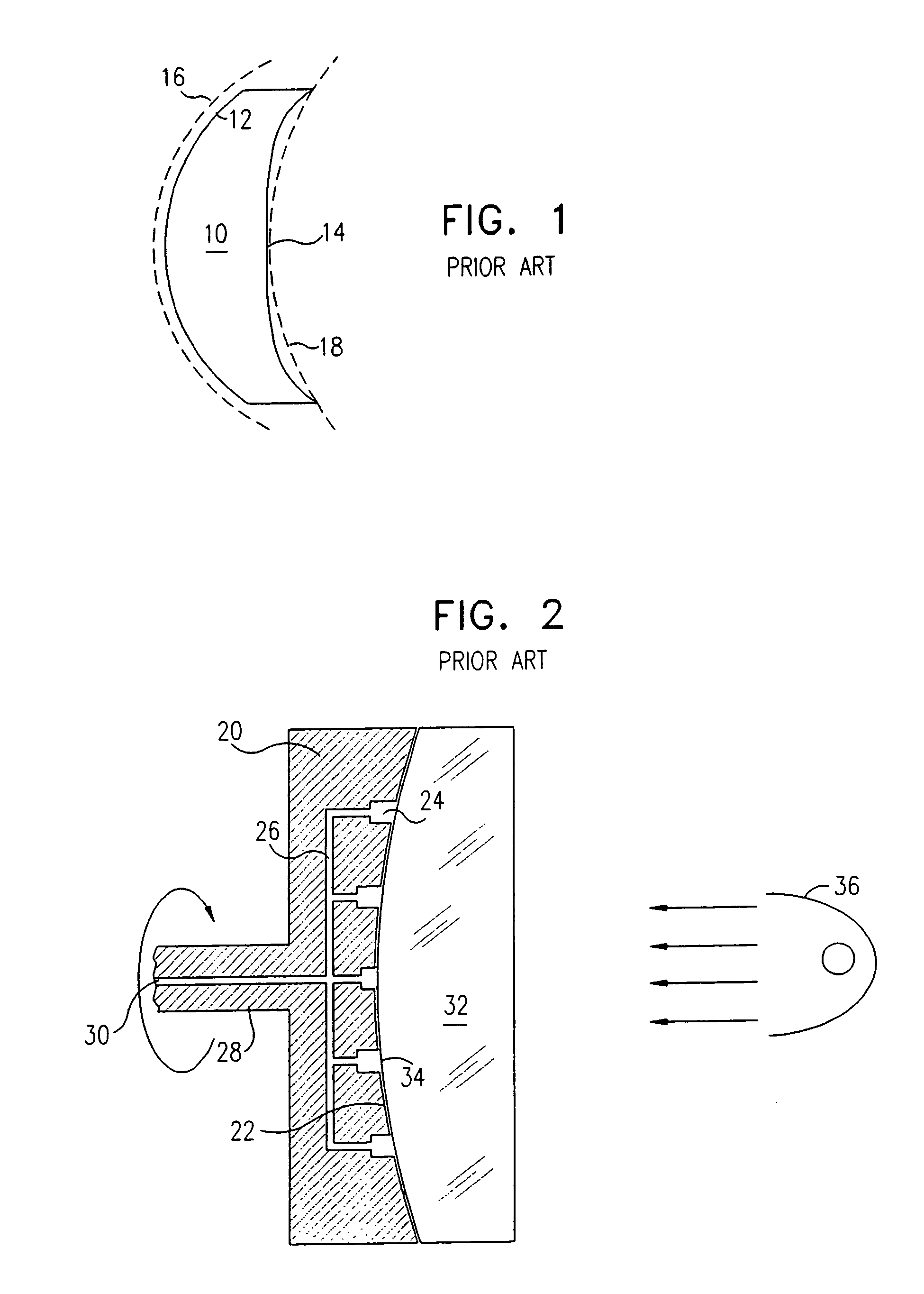
[0061]Reference is now made to FIG. 1, which illustrates schematically a prior art aspheric element 10, manufactured according to single point turning techniques hitherto available. The element could be a lens, a double-sided mirror or any other suitable double sided optical element, but in this preferred embodiment, a lens example is described. For use in an infra-red thermal imaging system, operating in the 8 to 12 μm or the 3 to 5 μm wavelength region, the lens may be made of a suitable material of the infra-red transmissive materials, such as polycrystalline or single crystal germanium, or CVD-grown zinc selenide or zinc sulphide, or gallium arsenide, silicon, or others. The first surface of the lens 12, which is the surface chucked in the machine, has a spherical form, as shown by the dotted arc of a circle 16. This surface is typically made by conventional lens grinding and polishing techniques. The opposite and second surface 14, which before diamond turning also had a spheri...


PUM

PropertyMeasurementUnit
Fractionaaaaaaaaaa
Sizeaaaaaaaaaa
Volumeaaaaaaaaaa

Abstract

A precision optical element is described, such as is used in thermal imaging systems in the infra-red, manufactured by means of single point machining, with both of its surfaces having an aspheric form, with or without the addition of a diffractive optics pattern. The element is produced while held in a novel vacuum chuck, whose support surface has a width in the radial direction significantly less than the size of the element, and which is aspherically machined to match the aspheric first surface of the element. A method whereby such an element can be produced by means of single point machining, such as diamond turning or fly cutting, is also described. Also described are new optical system designs and applications using such double-sided aspheric elements, thereby providing significant improvement over currently available optical systems.

Description

[0001]This application is a continuation of U.S. application Ser. No. 09 / 315,423 filed May 20, 1999 (the “Partent Application”), now U.S. Pat. No. 6,622,599, the entire disclosure of which is incorporated herein by reference. Thus, the present application claims priority from the Parent Application under 35 U.S.C. § 120.FIELD OF THE INVENTION[0002]The present invention relates to the field of precision aspheric optical elements, especially lenses, whose surfaces are produced by means of single point machining.BACKGROUND OF THE INVENTION[0003]Optical imaging systems using conventional spherical lenses generally require a large number of surfaces, and hence a large number of elements, in order to correct for optical aberrations present in the system, and thereby to improve the image quality. In principle, if the number of elements is unlimited, the optical system designer can propose spherical lens assemblies which can, in almost every case, simultaneously correct for all of the commo...

Claims


Application Information

Patent Timeline
IPC IPC(8): B23B41/04B23B1/00B24B13/005G02B5/18B24B13/04B24B41/06G02B3/00G02B3/04G02B3/08G02B13/14G02B27/00
CPCB24B13/005B24B41/061G02B3/04G02B5/189G02B13/14G02B27/0037G02B27/4211G02B27/4216G02B27/4227G02B27/4277B24B13/046Y10T82/148Y10T82/10Y10T82/125Y10T82/122Y10T82/149
Inventor BEN-MENACHEM, BARUCHZEREM, YAACOVASIDA, NISSIM
Owner OPHIR OPTRONICS SOLUTIONS
Why Eureka
Try Eureka