Non-linear equalizer system and method

Active Publication Date: 2006-04-18
HARRIS GLOBAL COMMUNICATIONS INC
View PDF2 Cites 71 Cited by
  • Summary
  • Abstract
  • Description
  • Claims
  • Application Information

AI Technical Summary

Problems solved by technology

The distortion may be manifest in intersymbol interference and the concomitant increase in bit error rate (“BER”) thereby reducing the performance of the communication system.
The distortion also increases the BER of data being transmitted by the waveform.
This type of solution may be useful for transmitt

Method used


Image

  • Non-linear equalizer system and method
  • Non-linear equalizer system and method
  • Non-linear equalizer system and method

Examples


Example

[0028]With reference to the drawings, like numerals represent like components and like relationships throughout the several drawings.

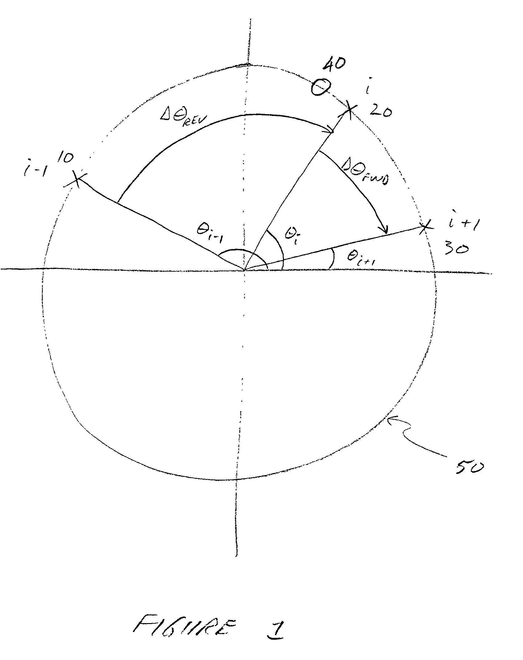
[0029]FIG. 1 is a diagrammatic view of a waveform constellation, such as a CPM constellation, showing the angular orientation of three notional successive symbols and the associated angles and phase differences. While a CPM waveform is discussed below, it is to be understood that the current invention may be used with other waveforms that exhibit phase distortion. The circle 50 is the locus of symbols for the given waveform constellation. The constellation may be a 4-ary, 8-ary, 16-ary, or other waveform. Points 10, 20, and 30 on the circle 50 represent a received preceding symbol, a received current symbol, and a received succeeding symbol, respectively. These points are also denoted throughout the specification and drawings with the subscripts (i−1), (i), and (i+1), respectively. The angular position of the symbols 10, 20, and 30 are denoted as θi−1,...


PUM


Abstract

A system and method for compensating for angular distortion of a received waveform is disclosed. One embodiment measures the angular position of a current symbol, the preceding symbol and the succeeding symbol, calculates the phase shift between the current symbol and a preceding symbol and the phase shift between the current symbol and a succeeding symbol, uses the phase shifts to enter a 2-D lookup table to extract a phase correction factor, then uses the phase correction factor to modify the angular position of the current symbol.

Description

[0001]This application claims the benefit of Provisional Application No. 60 / 242,752, filed Oct. 24, 2000.BACKGROUND OF THE INVENTION[0002]The present invention relates to compensating for distortion of a received waveform. The distortion may be manifest in intersymbol interference and the concomitant increase in bit error rate (“BER”) thereby reducing the performance of the communication system. More specifically, the invention relates to a novel system and method of compensating for phase distortion of a received waveform containing digital symbols at one of a predetermined number of phase angles. One of the received waveforms the present invention is directed towards is a continuous phase modulation (“CPM”) waveform received from a satellite transponder.[0003]Satellite transponders typically are comprised of a series of filters and hard-limiting amplifiers which modify the phase angle and amplitude of each symbol of the CPM phase constellation. Continuous phase modulation (“CPM”) ...

Claims


Application Information

Patent Timeline
IPC IPC(8): H03H7/40H03D3/22H04L27/00H04L27/233
CPCH04L27/2332H04L2027/0067
Inventor HESSEL, CLIFFORDNORRIS, JAMES A.
Owner HARRIS GLOBAL COMMUNICATIONS INC
Why Eureka
Try Eureka