Method and apparatus for diagnosing leakage in a fluid power system

a technology of fluid power system and leakage detection, applied in the direction of liquid/fluent solid measurement, volume measurement, volume measurement, etc., can solve the problems of failure of tubing, leakage, and leakage somewhere in the system, and achieve the effect of increasing fluid consumption

Inactive Publication Date: 2006-04-18
FESTO AG & CO KG
View PDF36 Cites 40 Cited by
  • Summary
  • Abstract
  • Description
  • Claims
  • Application Information

AI Technical Summary

Benefits of technology

[0008]It is an advantage of the present invention to provide a method and apparatus for detecting leakage in a fluid power system.
[0009]It is another advantage of the present invention to provide a method and apparatus for detecting the existence of a leak in a fluid power system and identify the location of the leak.
[0010]It an other advantage of the present invention to provide a method and apparatus for detecting the existence of a leak in a fluid power system and identify the location of the leak based on information provided by a flow sensor positioned in a line supplying pressurized fluid to a plurality of valves and signals used to shift the valves.
[0011]In the efficient attainment of these and other advantages the present invention includes a method of diagnosing leakage in a fluid power system including a fluid supply line operatively connected to a plurality of valves which are connected to a plurality of actuators.
[0012]The method includes the steps of: processing flow signals generated by a flow sensor disposed in the supply line to obtain fluid consumption over time; processing signals used to change the state of the plurality of valves to determine a plurality of episodes, each of the plurality of episodes corresponding to a pressurization of a particular branch of a particular actuator. The method further includes the steps of combining the flow signals with the signals used to change the state of the valves to calculate a change in air consumption value, ΔFC, for each valve change of state. The ΔFC values for each episode are compared to a predetermined reference number to determine deviation corresponding to a particular one of the plurality of episodes. The one of the plurality of episodes with the greatest deviation is identified and a signal indicating that a leak is present in the system and indicating the corresponding branch responsible for the leak is generated.
[0013]The present invention also provides a method for diagnosing an increase in fluid consumption in a fluid power system including a fluid supply line operatively connected to a plurality of valves which are each connected to a corresponding actuator by at least one branch, the at least one branch of each actuator being selectively pressurized and exhausted by the corresponding valves, the method comprising the steps of:

Problems solved by technology

During the use of fluid power components, it is almost inevitable that leakage will occur somewhere in the system.
Such leakage can occur by failure of the tubing, for example, by exposure to corrosive substances, abrasion as the tubing moves along with an actuator, or the tubing may inadvertently being pinched during the manufacturing process.
In addition, fittings which attach the tubing to the valves and actuators can become loose and permit leakage from the valve ports and / or cylinder ports.
Such leakage is undesirable and can have various deleterious effects.
For example, in pneumatic systems the pressurized air is provided by compressors which are expensive to operate.
Accordingly, even small leaks in a system left unattended, can lead to significant increase in operating costs for the system.
In addition, when pneumatic systems are used in environments where the condition of the ambient air is required to stay clean, unwanted air leakage can also lead to contamination and maintenance issues.
In the case of hydraulic systems, leaks will spill hydraulic oil out of the lines leading to contamination of the surrounding area.
While these leaks may be more easy to identify than in a pneumatic system, if left untreated, they can create significant maintenance issues.
In addition, leaks can affect actuator performance and the overall performance of the equipment.
Such inspections are time consuming and may be difficult to perform in a noisy industrial environment.
Hydraulic system leaks which result in the spillage of hydraulic oil can be seen, however, such leaks would only be uncovered if they are in an area where an operator can view the leak.
Such inspection methods will often miss small leaks and prevent maintenance from being done early on in a leakage event before any problems occur.
Methods relying on a multitude of sensors, however, require significant processing power and increase complexity.

Method used


Image

  • Method and apparatus for diagnosing leakage in a fluid power system
  • Method and apparatus for diagnosing leakage in a fluid power system
  • Method and apparatus for diagnosing leakage in a fluid power system

Examples


Embodiment Construction

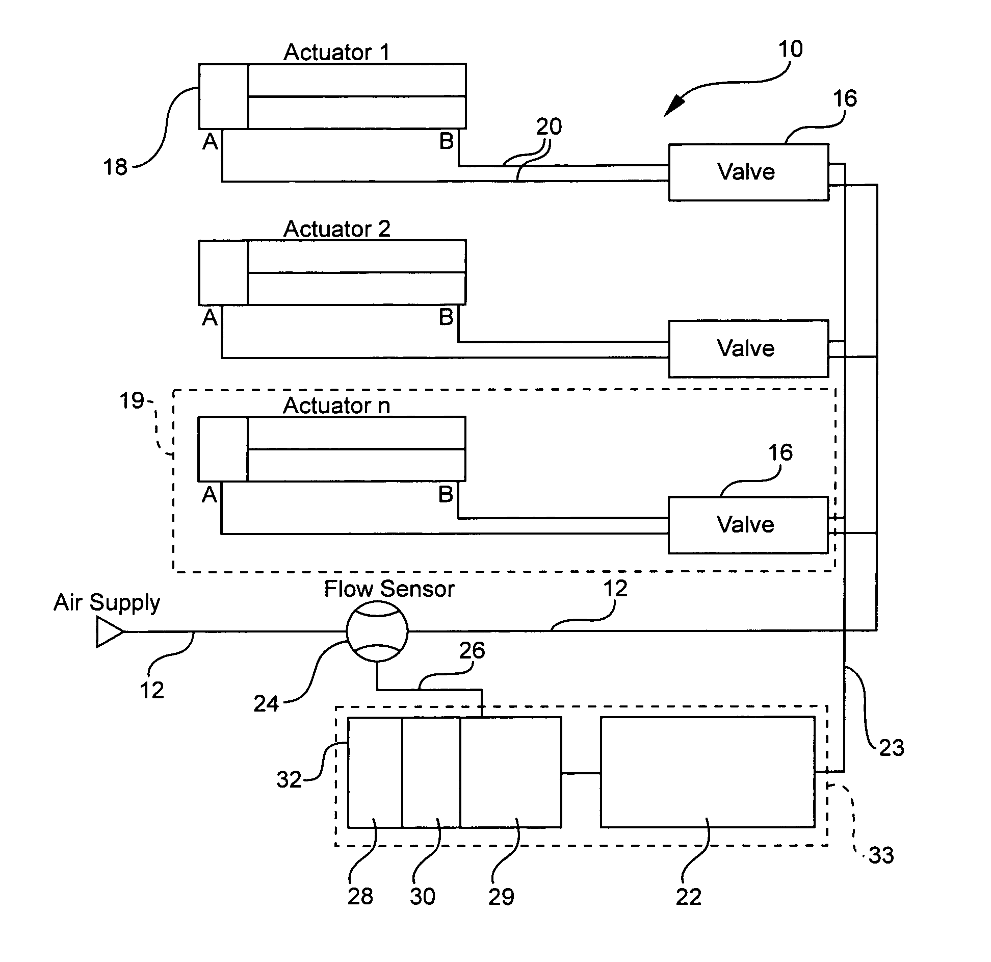
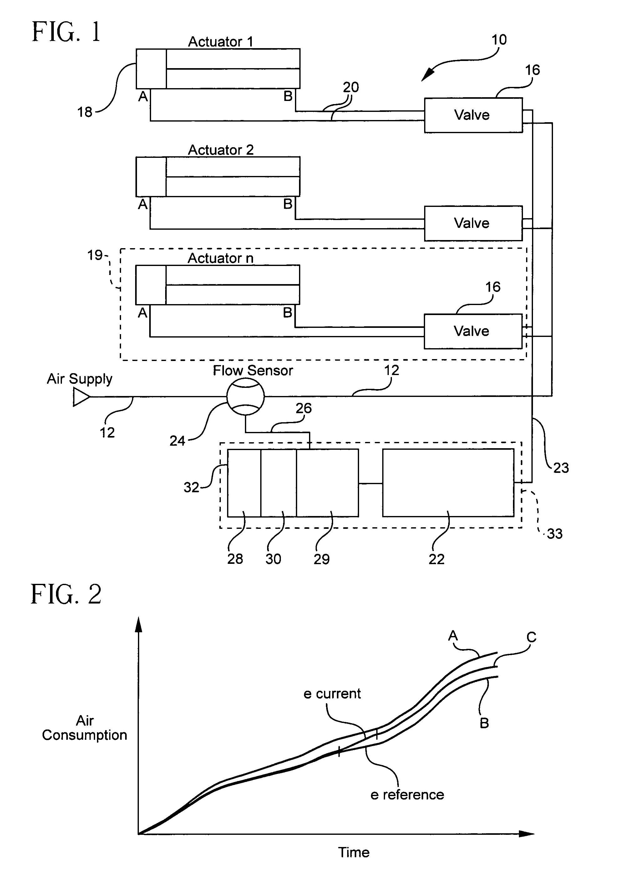
[0040]The present invention is directed to a method and apparatus for determining if a leak has occurred in a cyclic fluid power system and also for identifying the location of the leak. The present invention may be used in conjunction with a standard fluid power system which comprises a series of valves and actuators. As shown in FIG. 1, a fluid power system 10 formed in accordance with the present invention includes a supply line 12 providing pressurized fluid, which is operatively connected to one or more valves 16. Each valve 16 is connected to a corresponding actuator 18 forming a sub-system 19. In the preferred embodiment, air is the pressurized fluid, although other fluids such as hydraulic oil or the like could be used.

[0041]The valves and actuators are of a type well known in the art and may be employed in a variety of applications to operate a machine or control a process during manufacturing. The actuators 18 may be one of a variety of components including, for example, d...


PUM

PropertyMeasurementUnit
timeaaaaaaaaaa
total lengthaaaaaaaaaa
areaaaaaaaaaaa

Abstract

A method and apparatus of diagnosing leakage in a fluid power system including a fluid supply line operatively connected to a plurality of valves which are connected to a plurality of actuators. Flow signals generated by a flow sensor disposed in the supply line are processed to obtain fluid consumption over time values and signals used to change the state of the plurality of valves are processes to determine a plurality of episodes. Each of the plurality of episodes corresponds to a pressurization of a particular branch of a particular actuator. The flow signals and the signals used to change the state of the valves are combined to calculate a change in air consumption value for each valve change of state. The change in air consumption values for each episode are compared to a predetermined reference value to determine any deviation corresponding to a particular one of the plurality of episode. The one of the plurality of episodes and corresponding pressurized branch with the greatest deviation is identified. A signal is generated indicating both that a leak is present in the system and the branch responsible for the leak.

Description

FIELD OF INVENTION[0001]The invention relates to a method and apparatus for detecting leaks in a fluid power system, and more specifically for detecting the existence and location of leaks within a fluid power system.BACKGROUND OF THE INVENTION[0002]In the manufacturing environment, fluid power systems are typically used to automate machines, transport materials, and / or control processes. Such systems typically include a plurality of actuators that are operatively connected to valves. The actuators are connected to the valves by a series of tubing and fittings. The valves may be controlled by a number of devices such as microprocessors or programmable logic controllers or through analog control circuits. The fluid power systems typically run on compressed fluid such as air or hydraulic oil.[0003]During the use of fluid power components, it is almost inevitable that leakage will occur somewhere in the system. One common area of leakage is between the actuators and the valves. Such le...

Claims


Application Information

Patent Timeline
Patent Type & Authority Patents(United States)
IPC IPC(8): G01F17/00G01F23/00G01L7/00G01N11/00G06F19/00F15B19/00G01M3/26
CPCF15B19/005
Inventor KAMBLI, SACHINENGELHARDT, JENSBOEHM, CHRISTIAN
Owner FESTO AG & CO KG
Why Eureka
Try Eureka