Internal combustion engine provided with intake bypass control device

a control device and internal combustion engine technology, applied in the direction of electric control, machines/engines, mechanical equipment, etc., can solve the problems of low pressure ratio, difficult to find an exhaust gas turbocharger that matches the engine, and reduce the region

Inactive Publication Date: 2006-04-25
KOMATSU LTD
View PDF12 Cites 39 Cited by
  • Summary
  • Abstract
  • Description
  • Claims
  • Application Information

AI Technical Summary

Benefits of technology

[0009]An object of the present invention to provide an internal combustion engine that can avoid surging by means of a high pressure ratio and high rotational speed type compressor and obtain an excellent low-speed torque.

Problems solved by technology

However, a high pressure ratio turbocharger type compressor tends to reduce the region between the choke flow rate that is in the operable flow rate range and the surging flow rate when it is in operation.
Thus, it is difficult to find an exhaust gas turbocharger that matches the engine.
However, wide range type compressors normally show a low pressure ratio and are not adapted to a high rotational speed.
Therefore, a wide range type compressor is not suited for high pressure ratio supercharging.

Method used


Image

  • Internal combustion engine provided with intake bypass control device
  • Internal combustion engine provided with intake bypass control device
  • Internal combustion engine provided with intake bypass control device

Examples


1st embodiment

[1st Embodiment]

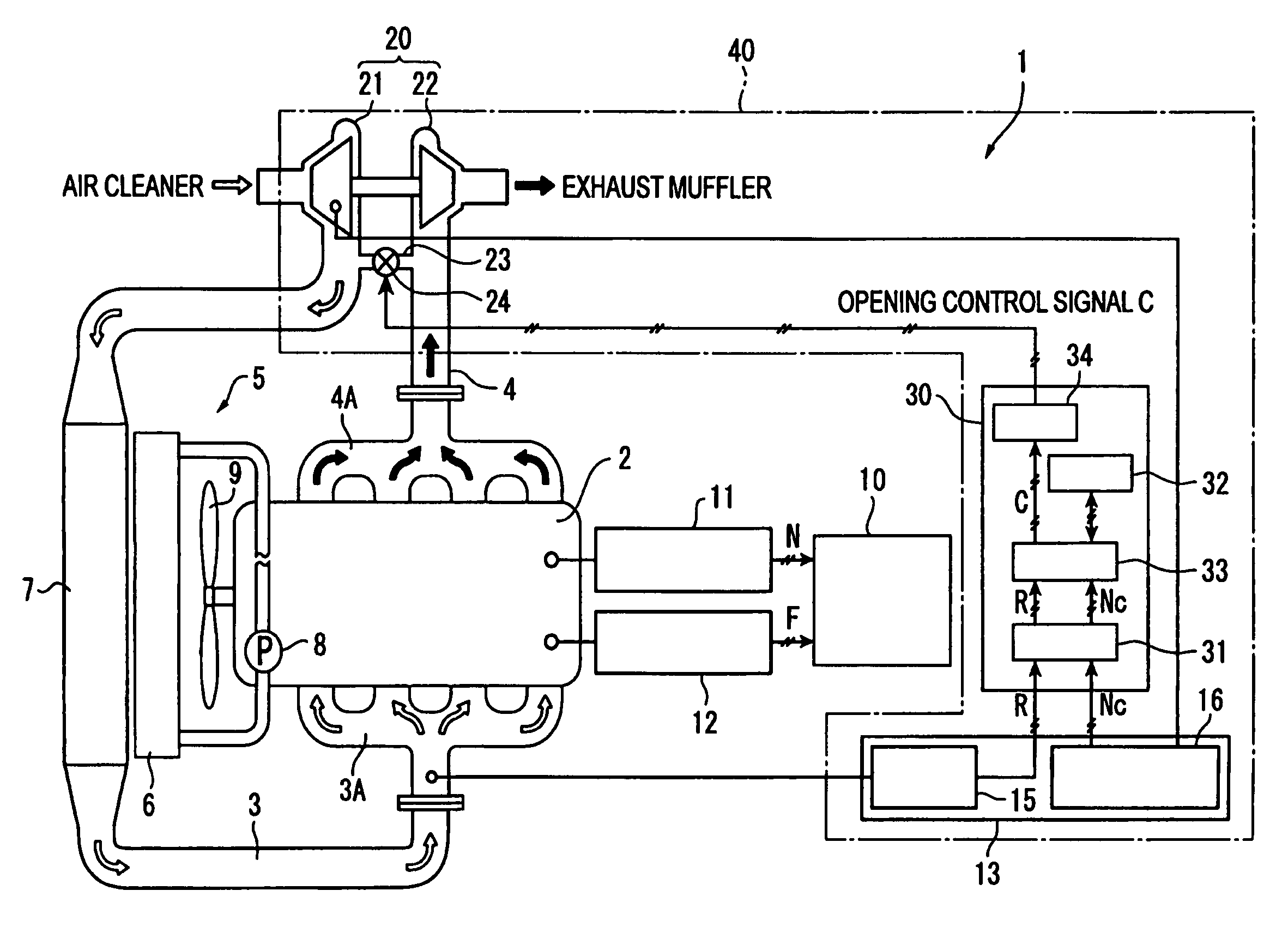
[0038]FIG. 1 is a schematic illustration of the system of a diesel engine (internal combustion engine) 1 to which the first embodiment is applied. Referring to FIG. 1, the diesel engine 1 has an engine main body 2 containing a plurality of combustion chambers (four in this embodiment) that are formed in the inside, an intake conduit 3 for supplying air to the combustion chambers, an exhaust conduit 4 for delivering exhaust gas to the outside of the combustion chambers, a cooling mechanism 5 for cooling the diesel engine 1, an engine controller 10 for controlling the operation of the engine main body 2 and an exhaust gas turbocharger (turbocharger) 20 adapted to compress the charge air for the purpose of supercharging the engine main body 2.

[0039]An intake manifold 3A is arranged between the intake conduit 3 and the engine main body 2 in order to distribute the air supplied from the intake conduit 3 among the combustion chambers. An exhaust manifold 4A is arranged bet...

2nd embodiment

[2nd Embodiment]

[0067]Now, the second embodiment of the present invention will be described below. The second embodiment differs from the above-described first embodiment in terms of the detector 13 of the intake control device 40 of the diesel engine 1.

[0068]FIG. 4 is a schematic illustration of the system of a diesel engine 1 to which the second embodiment is applied. Referring to FIG. 4, the intake control device 40 has a detector 13 for detecting the operating condition of the diesel engine 1 that is a compressor operating condition detector including a charge pressure detector 14 for detecting the charge pressure P of the compressor 21 and a charge air flow rate detector 15 for detecting the charge air flow rate R of the compressor 21. Both the charge pressure detector 14 and the charge air flow rate detector 15 are fitted to the intake manifold 3A so that it can detect the charge pressure P and the charge air flow rate R of the compressor 21 by detecting the intake pressure an...


PUM


Abstract

A bypass conduit (23) connects an outlet passage of a compressor (21) of an exhaust gas turbocharger (20) and an inlet passage of an exhaust turbine (22), and a bypass valve (24) is provided therein. When the operating condition of a diesel engine (1) is found to be in a low-speed and high-load region, the bypass valve (24) is controlled by means of a valve controller to adjust the bypass conduit (23) so as to open it. Then, the charge air partly flows into an exhaust conduit (4) to increase the rotational speed of the exhaust turbine (22) and hence the charge air flow rate raises the output of the diesel engine (1). Additionally, as the charge air flow rate is increased, the operating condition of a compressor (21) is prevented from approaching the surging range.

Description

BACKGROUND OF THE INVENTION[0001]1. Field of the Invention[0002]The present invention relates to an internal combustion engine provided with an intake bypass control device. More particularly, the present invention relates to an internal combustion engine provided with an exhaust gas turbocharger and an intake bypass control device adapted to drive a compressor by means of exhaust gas for intake air charging.[0003]2. Description of the Related Art[0004]Internal combustion engines such as gasoline engines and diesel engines that are provided with an exhaust gas turbocharger are known. The exhaust gas turbocharger revolves a turbine by utilizing the pressure of exhaust gas from the internal combustion engine and also drives a compressor by the torque of the turbine for intake air charging the internal combustion engine. Internal combustion engines provided with an exhaust gas turbocharger and also with a bypass circuit that allows the outlet passage of the compressor and the inlet pas...

Claims


Application Information

Patent Timeline
Patent Type & Authority Patents(United States)
IPC IPC(8): F02B33/44F02B37/00F02B37/12F02B37/16F02B3/06F02B29/04F02B37/10F02D23/00F02D23/02F02D41/00F02M25/07
CPCF02B37/10F02B37/16F02D23/02F02D41/0007F02B3/06F02B29/0425Y02T10/144F02M25/0707F02M25/0713F02M25/0722F02M25/0727F02M26/05F02M26/10F02M26/19F02M26/23Y02T10/12
Inventor ONODERA, YASUYUKINISHIYAMA, TOSHIHIKOITO, TAKUMI
Owner KOMATSU LTD
Why Eureka
Try Eureka