Thin film formation apparatus including engagement members for support during thermal expansion

a technology of thermal expansion and film formation apparatus, which is applied in the direction of coatings, chemical vapor deposition coatings, electric discharge tubes, etc., can solve the problems of adversely affecting the film thickness distribution, and achieve the effect of improving the apparatus performance, reducing the spacing between the first and second electrodes, and facilitating removal

Inactive Publication Date: 2006-04-25
SHARP KK
View PDF9 Cites 12 Cited by
  • Summary
  • Abstract
  • Description
  • Claims
  • Application Information

AI Technical Summary

Benefits of technology

[0011]In the inventive thin film formation apparatus, the first and second support members respectively support the first and second electrodes, and at least one of the first and second electrodes is movable in the thermal expansion direction. Therefore, when the first and second electrodes are heated to be thermally expanded, the at least one electrode moves in the thermal expansion direction, whereby the thermal expansion can be relieved. As a result, a variation in the spacing between the first and second electrodes can be reduced, thereby improving the performance of the apparatus. Since the at least one of the first and second electrodes is supported movably in the thermal expansion direction, the electrodes can easily be removed from the apparatus in the maintenance of the apparatus. This facilitates the maintenance of the plasma CVD apparatus.

Problems solved by technology

If the spacing between the anode electrode and the cathode electrode is varied, the apparatus fails to provide desired performance, thereby adversely affecting a film thickness distribution.

Method used


Image

  • Thin film formation apparatus including engagement members for support during thermal expansion
  • Thin film formation apparatus including engagement members for support during thermal expansion
  • Thin film formation apparatus including engagement members for support during thermal expansion

Examples


first embodiment

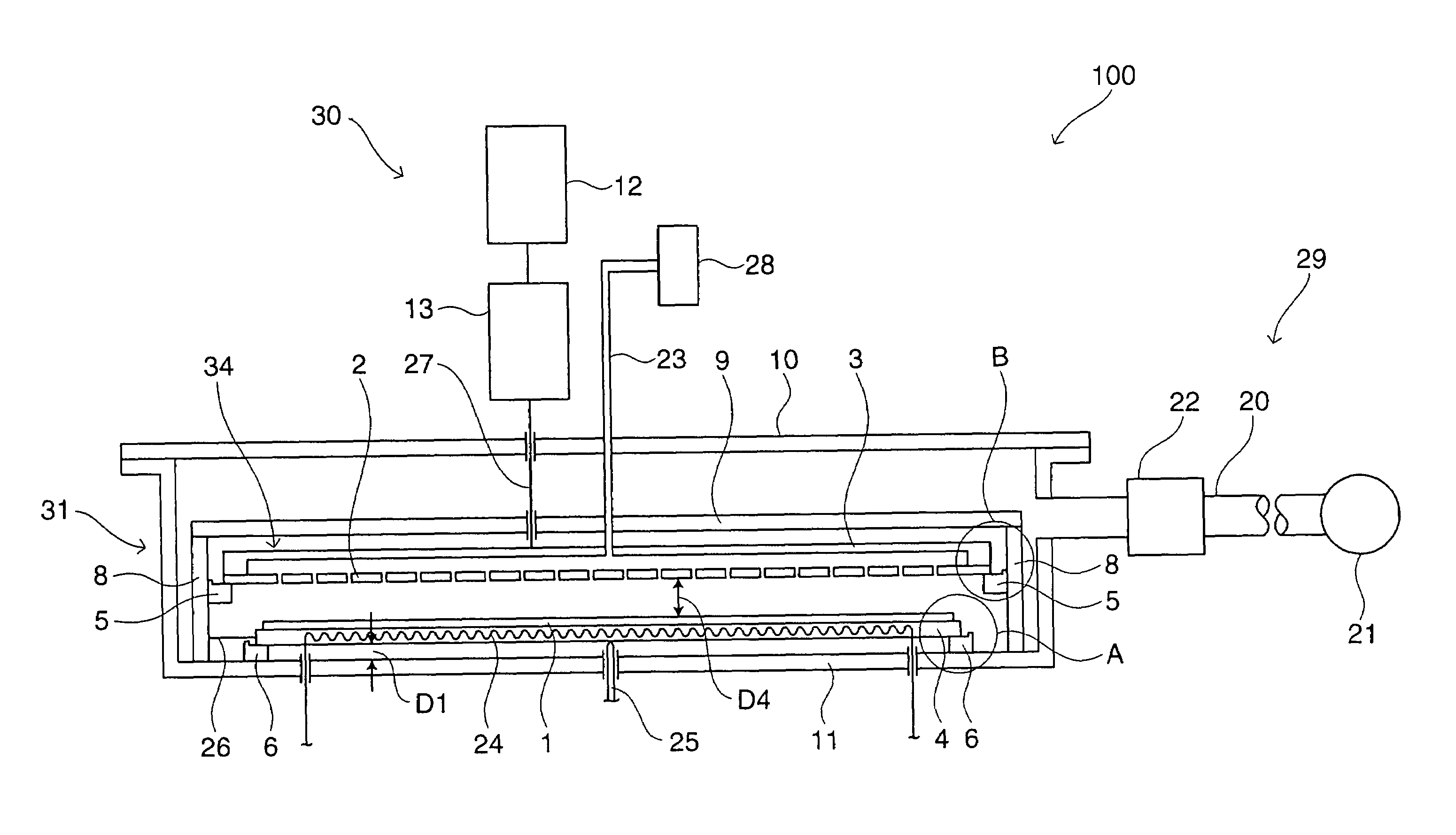
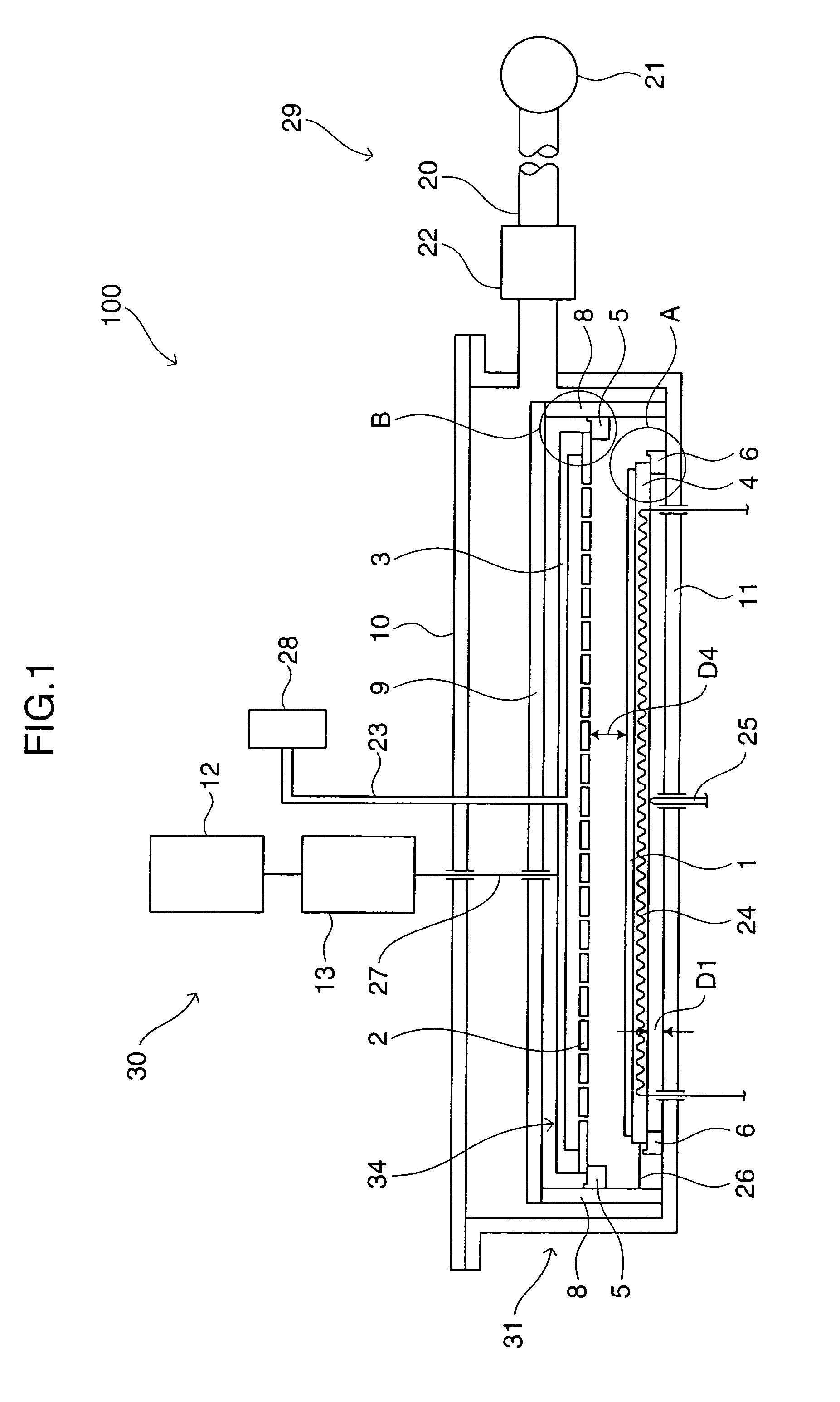
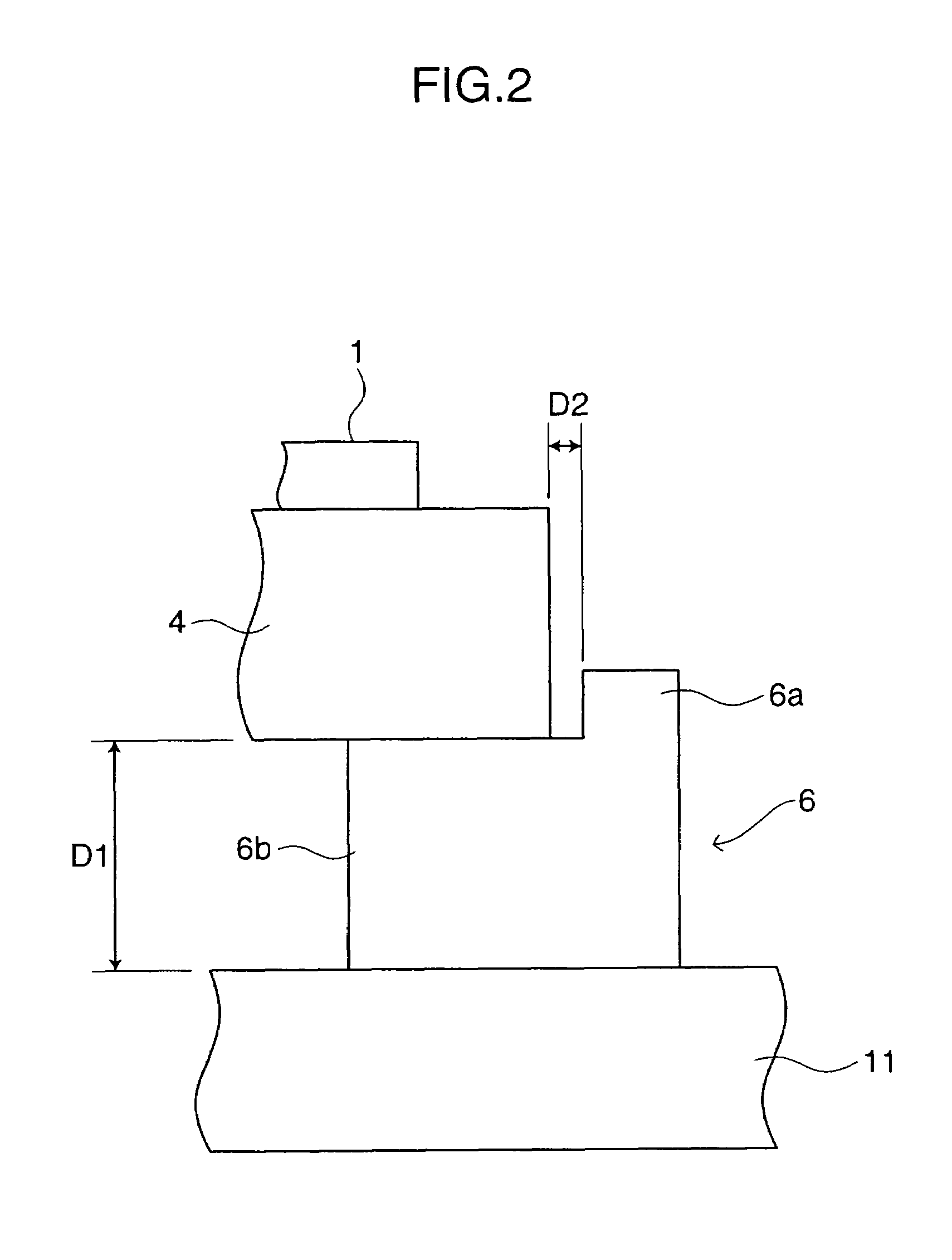
[0047]A thin film formation apparatus according to a first embodiment of the present invention will be described with reference to FIGS. 1 to 5. FIG. 1 is an explanatory diagram illustrating the overall construction of the thin film formation apparatus according to the first embodiment of the present invention. FIG. 2 is an enlarged diagram illustrating a portion of the apparatus indicated by a reference character A in FIG. 1, and FIG. 3 is an enlarged diagram illustrating a portion of the apparatus indicated by a reference character B in FIG. 1. FIG. 4 is a diagram for explaining how to support an anode electrode, and FIG. 5 is a diagram for explaining how to support a cathode electrode.

[0048]As shown in FIG. 1, the thin film formation apparatus 100 according to the first embodiment includes a chamber (reaction chamber) 31, a gas introduction section 28 for introducing a reactant gas into the chamber 31, an evacuation section 29 for exhausting the reactant gas from the chamber 31, ...

second embodiment

[0070]A thin film formation apparatus according to a second embodiment will be described with reference to FIG. 6. The thin film formation apparatus 200 according to the second embodiment has a two stage structure which includes two sets of anode electrodes 4 and cathode electrodes 34, and two sets of engagement members 5 and engagement members 6. More specifically, the engagement members 6 for supporting the anode electrode 4 of the second stage are provided on the cathode electrode 34 of the first stage. Thus, the two sets of anode electrodes 4 and cathode electrodes 34 are stacked vertically.

[0071]Support posts 8 supports the engagement members 5 of the first and second stages. Although the second embodiment provides the two stage structure, a three or more stage structure may be provided by repeating the aforesaid structure. In the second embodiment, the chamber 0.31, the gas introduction section 28, the evacuation section 29, the high frequency power source 30, the anode electr...

third embodiment

[0072]A thin film formation apparatus according to a third embodiment will be described with reference to FIGS. 7 and 8. FIG. 7 is a diagram for explaining how to support an anode electrode in the third embodiment, and FIG. 8 is a diagram for explaining how to support a cathode electrode in the third embodiment.

[0073]As shown in FIGS. 7 and 8, one of the four corners of the anode electrode 304 is fixed at a single point by a engagement member 306, and one of the four corners of the cathode 334 is fixed at a single point by a engagement member 305 in the third embodiment. The other three corners of each of the anode electrode 304 and the cathode electrode 334 are supported on corresponding engagement members 6, 5 movably in thermal expansion directions as in the first embodiment.

[0074]Cylindrical bosses 306a and 305a are provided upright on the engagement members 306 and 305, respectively. A hole 304a is formed in the one of the corners of the anode electrode 304 in association with ...


PUM

PropertyMeasurementUnit
sizeaaaaaaaaaa
sizeaaaaaaaaaa
temperatureaaaaaaaaaa

Abstract

A thin film formation apparatus for forming a thin film on a substrate is provided, which comprises: a reaction chamber; a gas introduction section for introducing a reactant gas into the reaction chamber; an evacuation section for exhausting the reactant gas from the reaction chamber; first and second planar electrodes provided in the reaction chamber; first and second support members which respectively support the first and second electrodes in parallel relation; a high frequency power source for applying high frequency power between the first and second electrodes; and a heating section for heating one of the first and second electrodes; wherein the substrate is placed on the heated electrode, and at least one of the first and second electrodes is supported movably in the direction of thermal expansion by the corresponding support member. With this arrangement, the variation in the spacing between the first electrode (anode electrode) and the second electrode (cathode electrode) can be reduced when the first and second electrodes are heated.

Description

CROSS-REFERENCE TO RELATED APPLICATIONS[0001]This application is related to Japanese application No.2002-299069 filed on Oct. 11, 2002, whose priority is claimed under 35 USC § 119, the disclosure of which is incorporated by reference in its entirety.BACKGROUND OF THE INVENTION[0002]1. Field of the Invention[0003]The present invention relates to a thin film formation apparatus and a thin film formation method employing the apparatus. More particularly, the invention relates to a thin film formation apparatus and a thin film formation method which utilize a plasma CVD process.[0004]2. Description of the Related Art[0005]One known method for forming a silicon thin film on a substrate is a plasma CVD process in which a reactant gas is decomposed by a plasma energy and the resulting material is deposited on a substrate. Further, a plasma CVD apparatus is known to be employed for this process.[0006]The plasma CVD apparatus typically includes a reaction chamber adapted to be evacuated to ...

Claims


Application Information

Patent Timeline
Patent Type & Authority Patents(United States)
IPC IPC(8): C23C16/50C23C16/509H01J37/32
CPCC23C16/5096H01J37/32009H01J37/32724H01J37/32568H01J37/32082
Inventor FUKUOKA, YUSUKEFUJIOKA, YASUSHIKISHIMOTO, KATSUSHIFUKUDA, HIROYUKINOMOTO, KATSUHIKO
Owner SHARP KK
Why Eureka
Try Eureka