Exhaust-gas muffler

a technology of exhaust gas and muffler, which is applied in the direction of combustion engines, mechanical devices, machines/engines, etc., can solve the problems of complex manufacture of resonant pipes of this kind, and achieve the effects of good noise attenuation, good attenuation characteristics, and high power

Inactive Publication Date: 2006-04-25
ANDREAS STIHL AG & CO KG
View PDF24 Cites 16 Cited by
  • Summary
  • Abstract
  • Description
  • Claims
  • Application Information

AI Technical Summary

Benefits of technology

[0006]A partition wall is mounted advantageously between the half shells. The partition wall forms especially a boundary of the resonance pipe. The partition wall can, however, at least partially delimit also the attenuation space of the muffler. It is especially provided that a first longitudinal section of the resonance pipe is bounded or delimited by the lower half shell and the partition wall and a second longitudinal section is delimited by the upper half shell and the partition wall. The resonance pipe can thereby be formed partially above and partially below the partition wall. In this way, the resonance pipe is not arranged only in one plane but in two planes and the length of the resonance pipe can be increased. Advantageously, the partition wall has a connecting opening between the two sections. In this way, the connection of the sections can be integrally configured with the partition wall. No additional components are necessary.
[0007]Advantageously, the upper and the lower half shells define the muffler housing. The resonance pipe is thereby configured to be integrated with the muffler housing. The muffler housing can be built up with a low number of components. Especially, the muffler housing essentially includes three components, namely, the upper and the lower half shells and the partition wall. A favorable arrangement and a good utilization of the component space, which is available, result when the outlet is arranged in the lower half shell which includes the inlet opening. To avoid additional components for the attachment of the exhaust-gas muffler, it is provided that the upper half shell, the partition wall and the lower half shell have attachment openings in those regions where they are tightly connected to each other.
[0010]High power and good noise attenuation result when the equivalent diameter of the diaphragm measured in millimeters is approximately 1 to 3 times (especially 1.2 to 2.4 times) the square root of the volume of the piston displacement of the engine measured in cubic centimeters. The equivalent diameter characterizes the diameter which a circularly-shaped diaphragm would have which corresponds to the cross-sectional form of the actual diaphragm. The equivalent diameter of the diaphragm is especially variable in dependence upon rpm. In this way, an adaptation of the noise attenuation characteristics to the particular engine rpm is achieved. The equivalent diameter of the resonance pipe amounts approximately to 2.5 to 6 times the square root of the volume of the piston displacement of the engine.
[0011]The equivalent diameter of the resonance pipe is advantageously approximately constant over the length thereof. The cross-sectional form of the resonance pipe is also substantially constant over the length thereof. For good attenuating characteristics and a high power of the engine, the length of the resonance pipe is matched to the rpm of the engine, especially to 60% to 100% of the rated rpm. For good exhaust-gas values, the exhaust-gas muffler includes a catalytic converter. Several resonance pipes are advantageously provided of which at least one is configured so that it can be switched in and out. In this way, an adaptation of the noise attenuating characteristics is possible. All resonance pipes are especially configured so that they can be switched in and out so that for each region of application one or several resonance pipes can be selected.

Problems solved by technology

A resonance pipe of this kind is complex to manufacture.

Method used


Image

  • Exhaust-gas muffler
  • Exhaust-gas muffler
  • Exhaust-gas muffler

Examples


Embodiment Construction

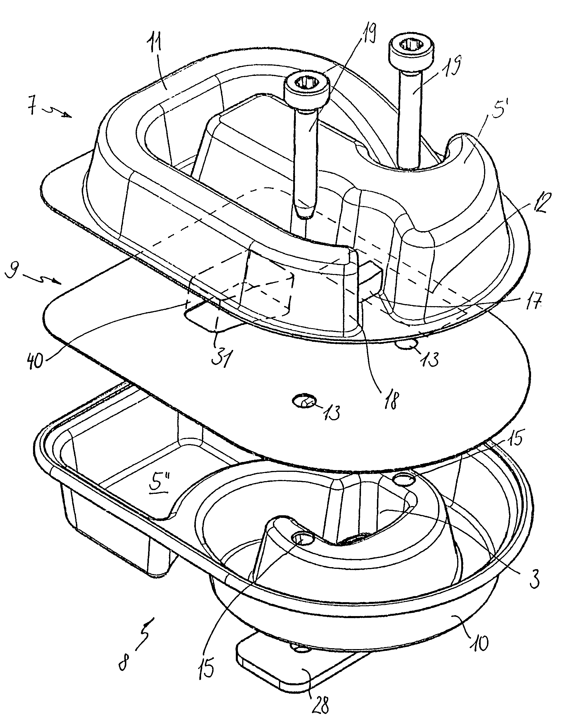
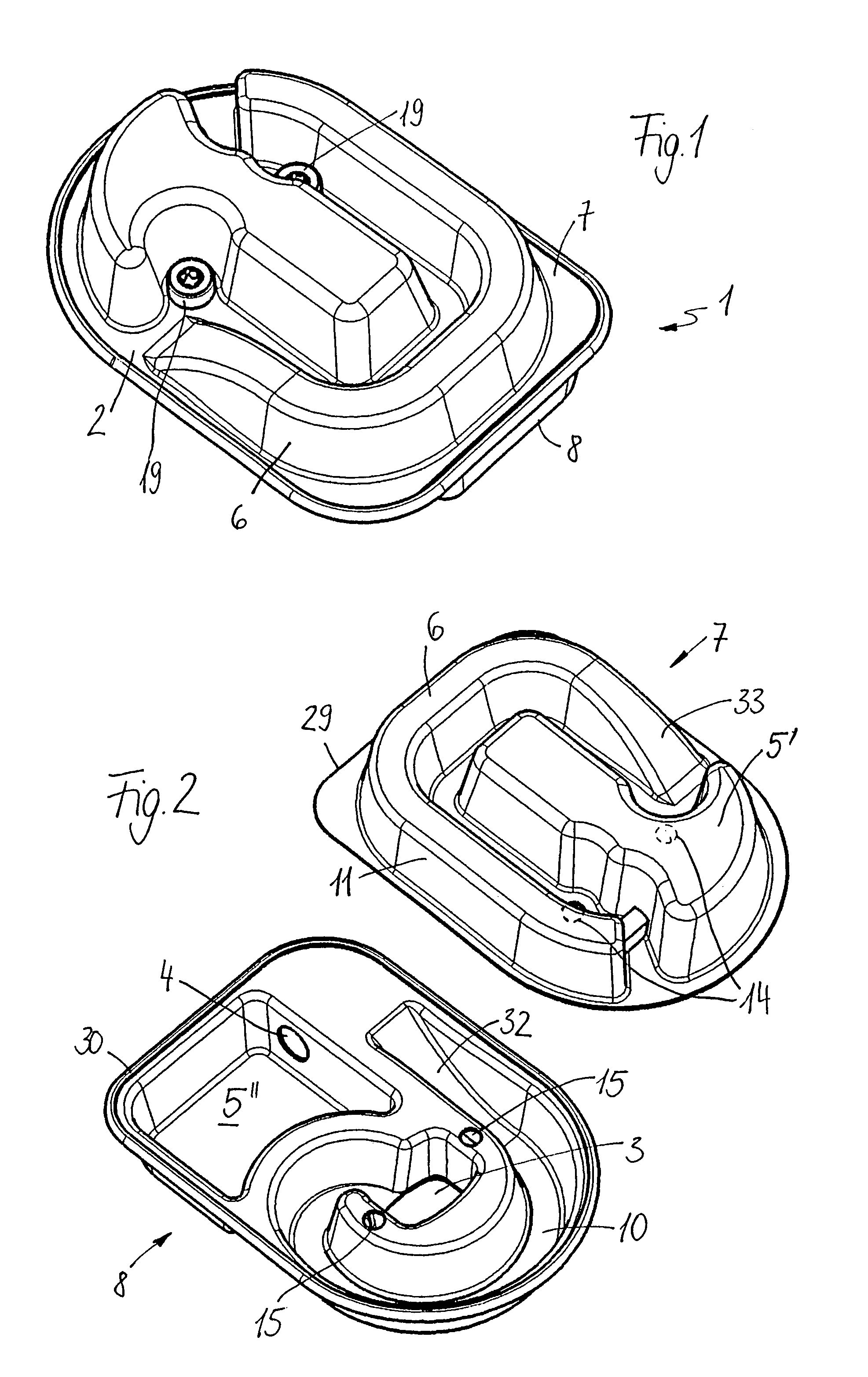
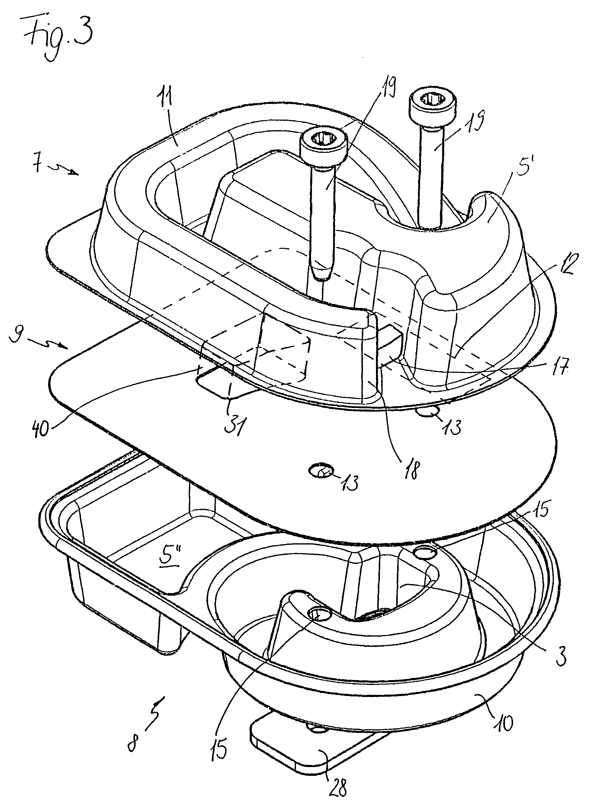
[0018]The exhaust-gas muffler 1 shown in FIG. 1 includes a muffler housing 2 which is formed from an upper half shell 7 and a lower half shell 8. The two half shells are formed from deep-drawn sheet metal. The half shells are connected to each other at their edges shown in FIG. 2. The edge 30 of the lower half shell 8 is flange connected to the edge 29 of the upper half shell 7. The upper half shell 7 has two attachment openings 14 and the lower half shell 8 has two attachment openings 15 for fixing the exhaust-gas muffler 1 to the engine. The attachment openings 14 and 15 lie atop each other when joining the half shells 7 and 8. The exhaust-gas muffler 1 can then be fixed with attachment screws 19 to the engine. The attachment screws project through the attachment openings 14 and 15.

[0019]An inlet opening 3 is formed in the lower half shell 8 facing toward the engine. The cross section of the inlet opening corresponds to the cross section of the combustion chamber outlet of the eng...


PUM


Abstract

An exhaust-gas muffler includes a muffler housing (2) having an inlet opening (3) and an outlet (4). The exhaust-gas muffler is especially for the internal combustion engine in a portable handheld work apparatus. At least one attenuating space (5, 5′, 5″) is configured in the exhaust-gas muffler (1). The exhaust-gas muffler (1) includes at least one resonance pipe (6) to increase power and to reduce the hydrocarbon emissions. The resonance pipe (6) is fluidly connected to the inlet opening (3) and the resonance pipe leads to a backflow of exhaust gases into the combustion chamber (22). For a simple manufacture, it is provided that the exhaust-gas muffler (1) includes lower and upper half shells (8, 7) via which the resonance pipe (6) is at least partially delimited.

Description

FIELD OF THE INVENTION[0001]The invention relates to an exhaust-gas muffler, especially an exhaust-gas muffler for an internal combustion engine in a portable handheld work apparatus.BACKGROUND OF THE INVENTION[0002]U.S. Pat. No. 6,698,194 discloses a two-stroke engine having an exhaust-gas muffler wherein a resonance pipe closed at one end is mounted between the outlet from the engine and the inlet into the exhaust-gas muffler. The resonance pipe is configured as a separate component which can be mounted in the attenuating space of the muffler so as to be wound in a spiral configuration. A resonance pipe of this kind is complex to manufacture.SUMMARY OF THE INVENTION[0003]It is an object of the invention to provide an exhaust-gas muffler of the kind described above which can be simply manufactured.[0004]The exhaust-gas muffler of the invention is for an internal combustion engine including for an internal combustion engine in a portable handheld work apparatus. The exhaust-gas muff...

Claims


Application Information

Patent Timeline
Patent Type & Authority Patents(United States)
IPC IPC(8): F01N1/08F01N1/02F01N13/18
CPCF01N1/02F01N13/1833F01N13/1888F01N13/1877F01N2590/06
Inventor HOCHE, FLORIANKLIMMEK, AXEL
Owner ANDREAS STIHL AG & CO KG
Why Eureka
Try Eureka