Coded welding consumable

a welding consumable and code technology, applied in the field of welding, can solve the problems of reducing the welding efficiency increasing the size of the wire, and increasing the complexity of the welding process, so as to improve the quality of the welding bead formation and increase the welding efficiency

Inactive Publication Date: 2006-04-25
LINCOLN GLOBAL INC
View PDF46 Cites 170 Cited by
  • Summary
  • Abstract
  • Description
  • Claims
  • Application Information

AI Technical Summary

Benefits of technology

[0033]Another and/or alternative object of the present invention is the provision of an apparatus and method of welding that improves the quality of weld bead formation during a welding process.
[003...

Problems solved by technology

Electric arc welding is a complicated process wherein numerous interrelated and non-interrelated parameters affect the deposition of molten metal to a weld pool in performing a welding operation.
The die progressively wears during production, whereby the wire size gradually increases and eventually becomes oversized with respect to the specification.
While it is possible to tightly control the wire diameter during production such as by frequent replacement of dies, such production for most practical purposes is economically unacceptable...

Method used


Image

  • Coded welding consumable
  • Coded welding consumable
  • Coded welding consumable

Examples


Embodiment Construction

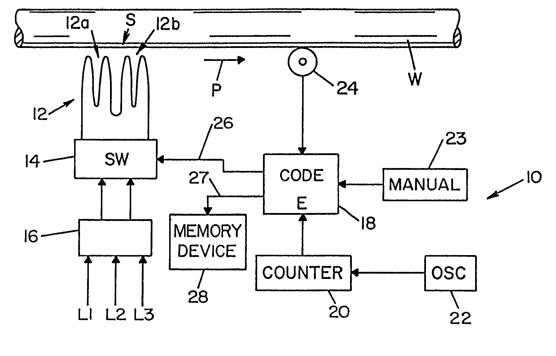
[0061]Referring now in greater detail to the drawings, wherein the showings are for the purpose of illustrating preferred embodiments of the invention only and not for the purpose of limiting the invention, FIG. 1 illustrates a section of metal welding wire W which is of indeterminate length and, in connection with the manufacture thereof, is drawn and wrapped onto a spool or reel. In use, as will become apparent hereinafter, the reel is mounted on welding apparatus in association with a wire feeding device by which the wire is payed from the reel and fed to the welding station of the apparatus. As the wire is drawn in connection with the manufacturing process, it is moved along a path as indicated by arrow P in FIG. 1 and, in accordance with the present invention, relative to an encoding unit 10 provided along the path and which includes a writing component 12 at an, encoding station S along path P. In this embodiment, writing component 12 is shown as an inductor coil having adjace...


PUM

PropertyMeasurementUnit
Widthaaaaaaaaaa
Areaaaaaaaaaaa
Frequencyaaaaaaaaaa

Abstract

Information pertaining to characteristics of consumables such as metal welding electrode wire and shielding gas and which characteristics are useful in connection with adjusting welding parameters in an arc welding process and/or selecting between operating modes in a welding system are encoded on welding wire and/or on other memory components such as bar code labels and tags, RFID cards and tags, IC cards, and Touch Memory buttons, and the memory device is scanned prior to and/or at the point of use of the welding wire or shielding gas for enabling tracking of product distribution, manual and/or automatic selection of an operating mode for the welding system, manual and/or automatic adjustment of welding parameters in a given operating mode, consumables inventory, and the like.

Description

[0001]The present invention is a continuation-in-part of U.S. patent application Ser. No. 09 / 842,103 filed Apr. 26, 2001 entitled “CODED AND ELECTRONICALLY TAGGED WELDING WIRE,” now U.S. Pat. No. 6,536,660 which is a divisional of U.S. patent application Ser. No. 09 / 336,574 filed Jun. 21, 1999, now U.S. Pat. No. 6,267,291.INCORPORATION BY REFERENCE[0002]Incorporated herein by reference for background information is U.S. Pat. No. 5,692,700 to Bobeczko which is assigned to the assignee of the present application and which discloses the provision of a bar code on a cover and / or reel to identify the type and size of the welding wire on the reel. Also incorporated by reference is Blankenship U.S. Pat. No. 6,267,291 which is assigned to the assignee of the present application and which discloses the encoding of filler wire to control an automatic or semi-automatic welding apparatus.BACKGROUND OF THE INVENTION[0003]This invention relates to the art of welding and, more particularly, to the...

Claims


Application Information

Patent Timeline
IPC IPC(8): G06F17/00B23K9/10B23K35/40G06K1/12G06K7/08G06K17/00G06K19/06G06K19/077
CPCB23K9/1062B23K35/40G06K1/125G06K19/07749G06K19/07758G06K7/084G06K2019/06253G06K2017/0087
Inventor BLANKENSHIP, GEORGE D.
Owner LINCOLN GLOBAL INC
Why Eureka
Try Eureka