[0007]An
advantage of the invention is seen in that only very few controllable directional valves are needed whereby space for mounting components and costs are saved. A further
advantage of the invention is that the compressor can transfer pressurized medium from the pressurized medium chambers into the pressurized medium spaces and vice versa. In this way, rapid control speeds are achieved when controlling up or controlling down the level control system. A further
advantage of the invention is that a higher pressure can be generated in the pressurized medium chambers than the actual compressor end pressure of the compressor because the compressor inducts precompressed pressurized medium from one of the two pressurized medium spaces and can transfer the same into the pressurized medium chambers. The compressor can therefore be dimensioned smaller in order to generate the
maximum pressure in the pressurized medium chambers whereby space for mounting components can be saved. A further advantage is that a pressurized medium space subjected to leakage (which then has
atmospheric pressure) can still carry out an up-control operation with the pressurized medium in the other pressurized medium space.
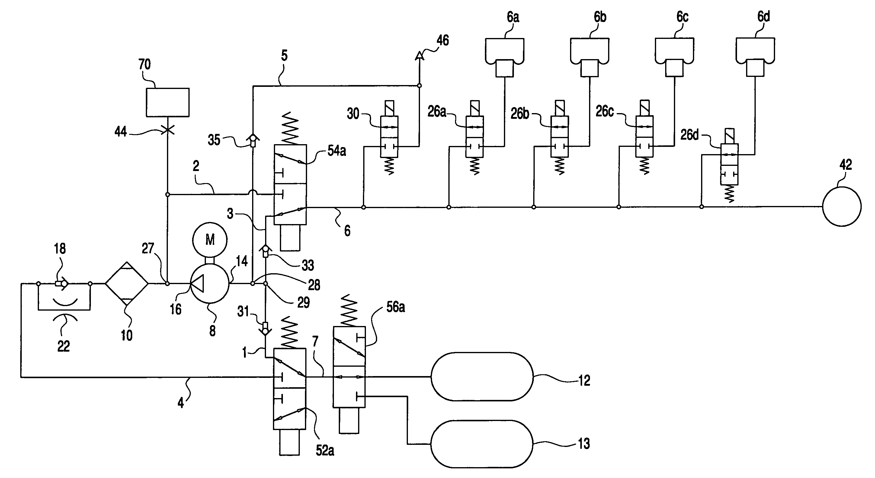
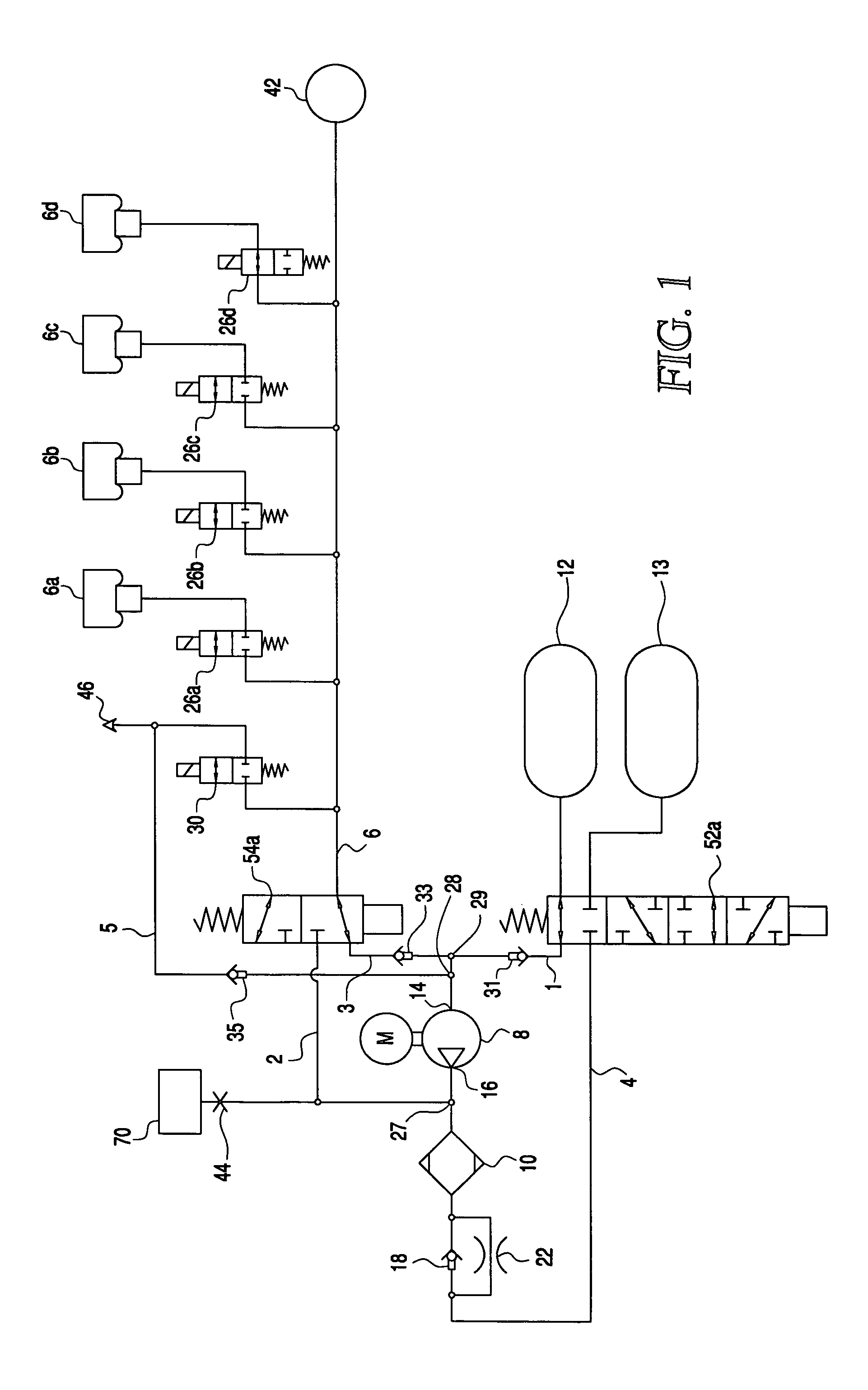
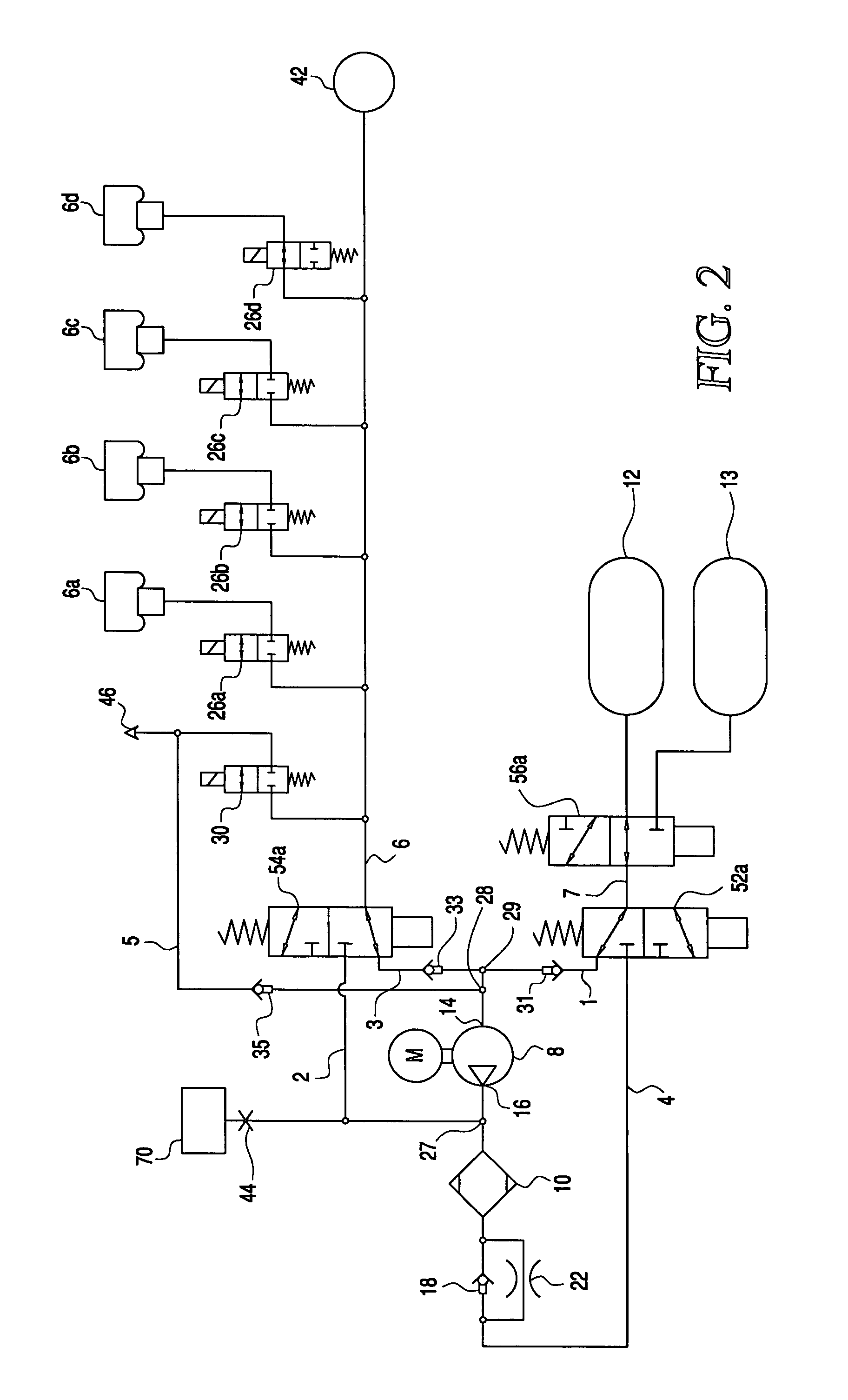
[0008]According to another feature of the invention, the closed level control system includes at least three controllable directional valves of which each has at least two switching states. The first pressurized
air line is switched through with the first controllable
directional valve and the second pressurized
air line is switched through with the second controllable
directional valve and the fourth pressurized
air line is blocked by the first controllable directional valve and the third pressurized air line is blocked by the second controllable directional valve when pressurized air is to be transferred from one of the two pressurized medium spaces into a pressurized medium chamber. The first and second controllable directional valves are then in a first switching state. The third pressurized air line is switched through by the second controllable directional valve and the fourth pressurized air line is switched through by the first controllable directional valve and the first pressurized air line is blocked by the first controllable directional valve and the second pressurized air line is blocked by the second controllable directional valve when pressurized air is to be transferred from a pressurized medium chamber into one of the two pressurized medium spaces. The first and second controllable directional valves are then in a first switching state. A connection of the first controllable directional valve to the first pressurized medium space is established when the third directional valve is in its first switching state and a connection of the first controllable directional valve to the second pressurized medium space is established when the third directional valve is in its second switching state.
[0009]The advantage of the above feature is that cost-effective standard directional valves can be used in order to connect the compressor input to the pressurized medium chambers or the compressor output to the pressurized medium supply spaces.
[0010]According to another feature of the invention, a
check valve is disposed in the first pressurized air line between a
common point and the first controllable directional valve with which the first pressurized air line can be switched through. This
common point connects the first pressurized air line and the third pressurized air line to the compressor input and the
check valve is opening toward the compressor input. A further
check valve, which is opening toward the compressor input, lies in the third pressurized air line between the
common point and the second controllable directional valve with which the third pressurized air line is switched through.
[0011]The advantage of the embodiment of the invention is that, in a specific position of the first and second directional valves, an overflow of pressurized medium from the pressurized medium chambers into the pressurized medium space, which is then switched through by the third directional valve, is not possible and this is independent of whether the air pressure in the pressurized medium chambers is greater or less than the air pressure in the switched-through pressurized medium supply space. In the
rest state of the level control system (that is, when no control takes place), the controllable directional valves can, for example, be transferred into this position so that an unintended overflow of pressurized medium between the pressurized medium chambers and the switched-through pressurized medium space cannot take place. Furthermore, in this defined state of the controllable directional valves, a
pressure measurement in the pressurized medium chambers is possible in a simple manner with the aid of a
pressure sensor.
[0012]A further advantage of this embodiment of the invention is that the third controllable directional valve can be so switched into the
rest state of the level control system that the pressurized medium space at the higher
pressure level (which is preferably higher than the
pressure level in the pressurized medium chambers) communicates with the compressor input so that no pressurized air can overflow from the pressurized medium chambers into this pressurized medium space. Preferably, the second controllable directional valve is in its second switch position so that no pressurized medium can overflow from the pressurized medium chambers into the compressor or the air dryer.

