Scanning laser microscope having a spectrum image positional correction
a laser microscope and spectrum image technology, applied in the field of scanning laser microscopes, can solve the problems of affecting the accuracy of spectral data, the displacement of the spectrum image position, and the manufacture error of the rotating bearing portion of the turbin
- Summary
- Abstract
- Description
- Claims
- Application Information
AI Technical Summary
Benefits of technology
Problems solved by technology
Method used
Image
Examples
first embodiment
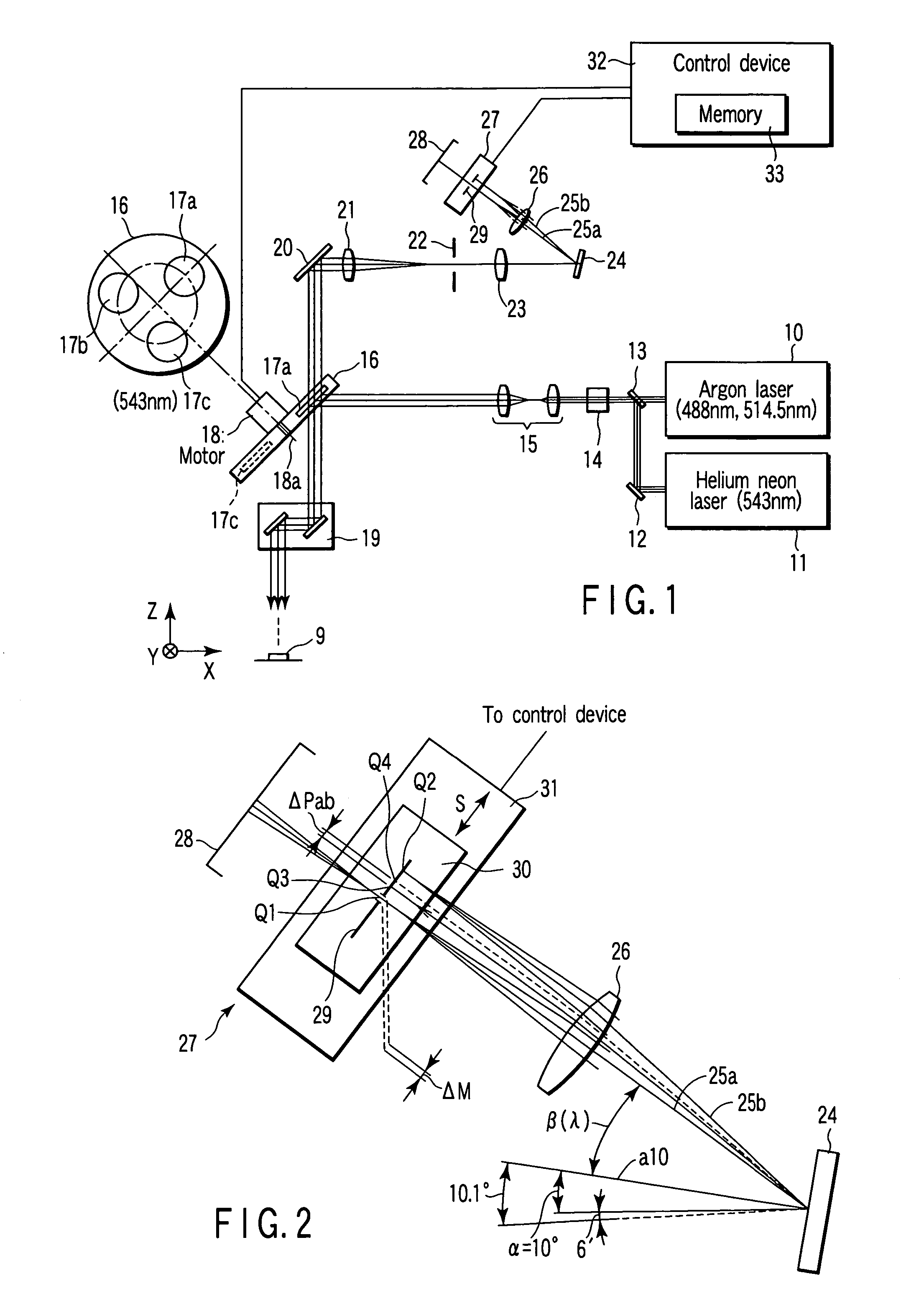
[0033]A first embodiment according to the present invention will now be described hereinafter with reference to the accompanying drawings.
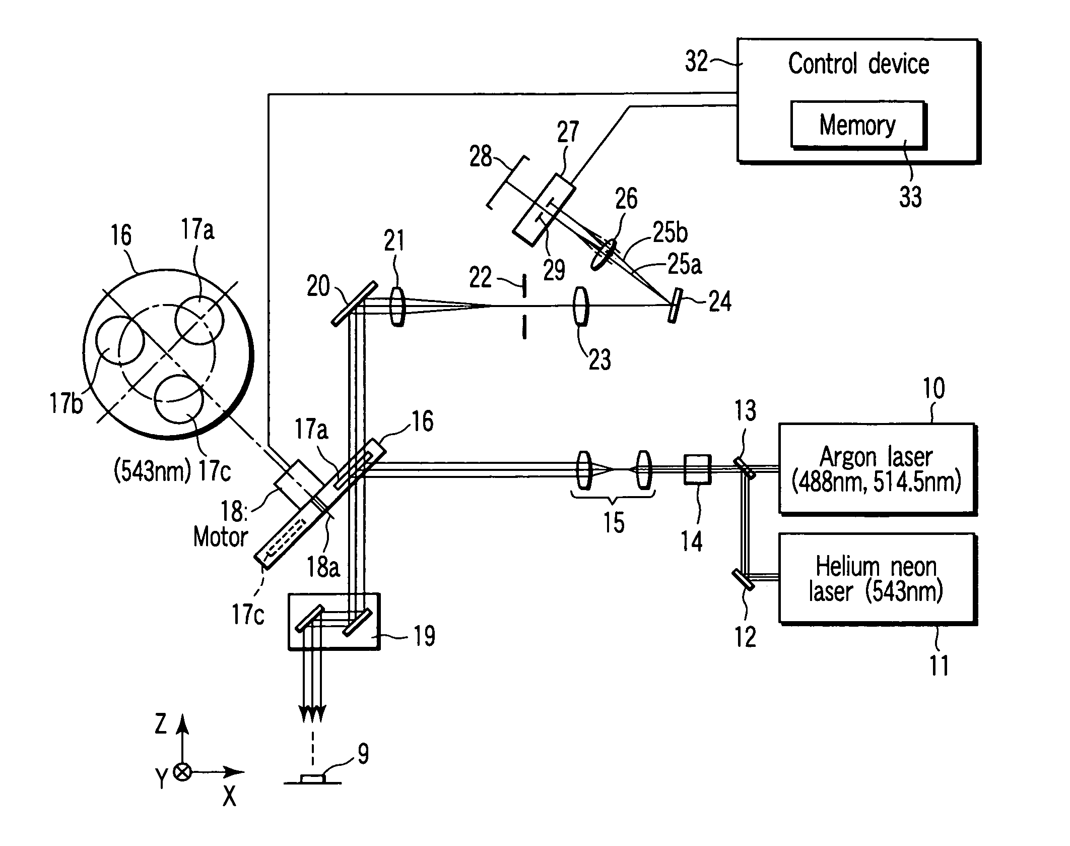
[0034]FIG. 1 is a structural view of a scanning laser microscope. An argon laser 10 outputs laser beam having wavelengths of 488 nm and 514.5 nm. A helium neon laser 11 outputs laser beam having a wavelength of 543 nm.
[0035]A mirror 12 is provided on a light path of laser beam outputted from the helium neon laser 11. A beam-combining dichroic mirror 13 is provided at an intersection between a light path of laser beam outputted from the argon laser 10 and a reflection light path of the mirror 12. The beam-combining dichroic mirror 13 combines laser beam outputted from the argon laser 10 and laser beam outputted from the helium neon laser 11 on one light path.
[0036]An acousto-optic tunable filter (which will be referred to as an AOTF hereinafter) 14 and a beam expander 15 are provided on the light path of the laser beam combined and emitted by the b...
second embodiment
[0100]A second embodiment according to the present invention will now be described with reference to the accompanying drawings.
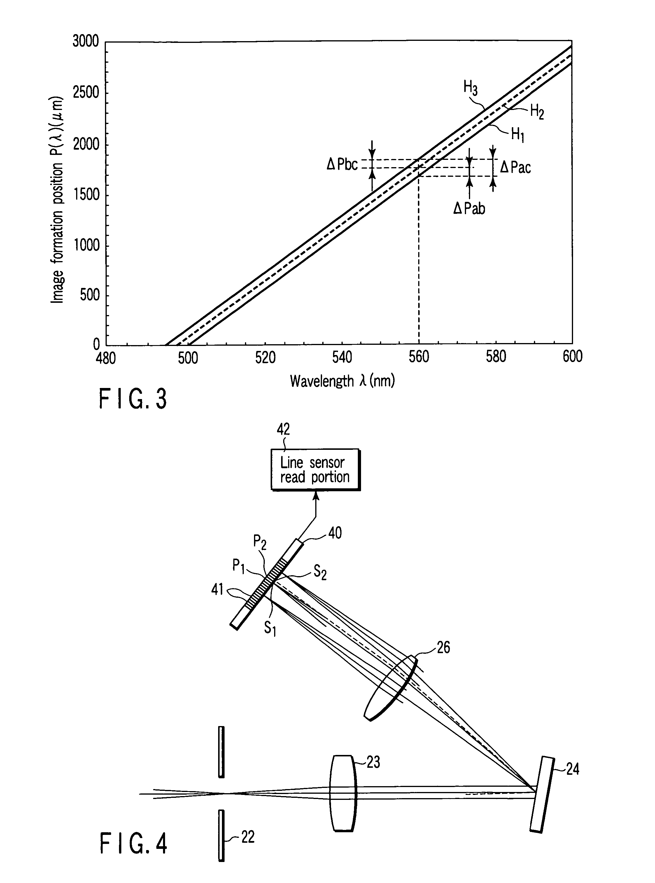
[0101]FIG. 4 is a structural view showing a characteristic part in a scanning laser microscope. It is to be noted that any other parts are equal to those depicted in the structural view of FIG. 1. In the scanning laser microscope, a line sensor (photodetector) 40 is provided in place of the variable slit unit 27 and the photodetector 28 in the first embodiment.
[0102]The line sensor 40 is constituted by arranging a plurality of light receiving pixels (detection portions) 41 in an array form. The line sensor 40 is arranged at a spectrum image formation position. The line sensor 40 is provided in a direction along which an arrangement direction of the respective light receiving pixels 41 matches with the spectrum direction.
[0103]An arrangement position of each light receiving pixel 41 corresponds to a band area of each spectrum. Therefore, a necessary band area...
third embodiment
[0116]A third embodiment according to the present invention will now be described with reference to the accompanying drawings. It is to be noted that like reference numerals denote parts equal to those in FIG. 1, thereby eliminating their detailed explanation.
[0117]FIG. 5 is a structural view showing a scanning laser microscope. A spectral beam splitter turret 50 is provided on a light path of light which have been transmitted through a collimator lens 23. The spectral beam splitter turret 50 is formed into a discoid shape. In the spectral beam splitter turret 50, a plurality of attachment holes, e.g., three attachment holes are provided on the same circumference at equal intervals.
[0118]A spectral dichroic mirror (second beam splitter) 51 and a reflection mirror 52 are attached to two attachment holes in the plurality of attachment holes. The reflection mirror 52 reflects all the light. It is to be noted that respective exciting dichroic mirrors 17a to 17c attached to the beam spli...
PUM
 Abstract
Description
Claims
Application Information
 - R&D
- Intellectual Property
- Life Sciences
- Materials
- Tech Scout
- Unparalleled Data Quality
- Higher Quality Content
- 60% Fewer Hallucinations
Browse by: Latest US Patents, China's latest patents, Technical Efficacy Thesaurus, Application Domain, Technology Topic, Popular Technical Reports.
© 2025 PatSnap. All rights reserved.Legal|Privacy policy|Modern Slavery Act Transparency Statement|Sitemap|About US| Contact US: help@patsnap.com


