Modified polar amplifier architecture

a technology of polar amplifiers and amplifiers, applied in the field of electronic devices, can solve the problems of linear amplifiers operating in these types of signals with very inefficient efficiency, the cost of the amplifier scales with its peak power, and the size and cost of the power amplifier are generally proportional, so as to achieve the effect of mitigating signal distortion and out-of-band (oob) emissions associated with the signal

Active Publication Date: 2006-04-25
NORTHROP GRUMMAN SYST CORP
View PDF14 Cites 39 Cited by
  • Summary
  • Abstract
  • Description
  • Claims
  • Application Information

AI Technical Summary

Benefits of technology

[0009]In another aspect of the invention, an amplifier system is provided that includes a power amplifier, an input path, a supply path, a mode selector and a correction path. The power amplifier is operative to amplify an input signal to provide an amplified output signal. The input path is coupled to an input of the power amplifier and the supply path is coupled to a supply of the power amplifier. The mode selector controls the operation of the amplifier system between a polar mode and a signal restoration mode based on an envelope amplitude level of the input signal relative to a threshold level. The correction path mitigates signal distortion and out-of-band (OOB) emissions associated with the amplified output signal in the polar mode and provides at least a substantial portion of the amplified output signal in the signal restoration mode.

Problems solved by technology

Therefore, the operation of linear amplifiers in these types of signals is very inefficient, since the amplifiers must have their supply voltage sized to handle the large peak voltages even though the signals are much smaller a substantial portion of the time.
Additionally, the size and cost of the power amplifier is generally proportional to the required peak output power of the amplifier.
The cost of the amplifier scales with its peak power.
Several other circuit costs including heat sinks and DC-DC power supplies scale inversely to peak power and dissipated heat (which results from the electrical inefficiency).
Related base station costs of AC-DC power supplies, back-up batteries, cooling, and circuit breakers also scale inversely with efficiency as does the electrical operating costs.
Clearly, improving DC-RF efficiency is a major cost saver both for manufacturing and operation.
However, non-linear amplifiers can only be employed with constant envelope signals, such as frequency modulations (FM) and certain forms of phase modulation (PM), signals with modulated amplitudes cause severely distorted outputs from these classes of amplifiers.
Polar amplifiers have demonstrated very high efficiency but can distort signals and cause significant amounts of OOB emissions.
Most available linearization techniques are not applicable to polar amplifiers because of their dual signal nature, making it difficult to reduce OOB emissions.
If the signal crosses through a zero-amplitude point, referred to as zero crossings, it may cause the polar amplifier to cut-off and / or require an extremely rapid and difficult phase change in the constant envelope phase modulated path.
If the signal varies over a large dynamic range it may cause the polar amplifier to operate with very low supply (e.g., drain) voltages resulting in additional signal distortion and can cause the amplifier to shutoff when the supply voltage becomes too low.
As a result, the polar amplifier has only been employed with a limited range of waveforms.

Method used


Image

  • Modified polar amplifier architecture
  • Modified polar amplifier architecture
  • Modified polar amplifier architecture

Examples


Embodiment Construction

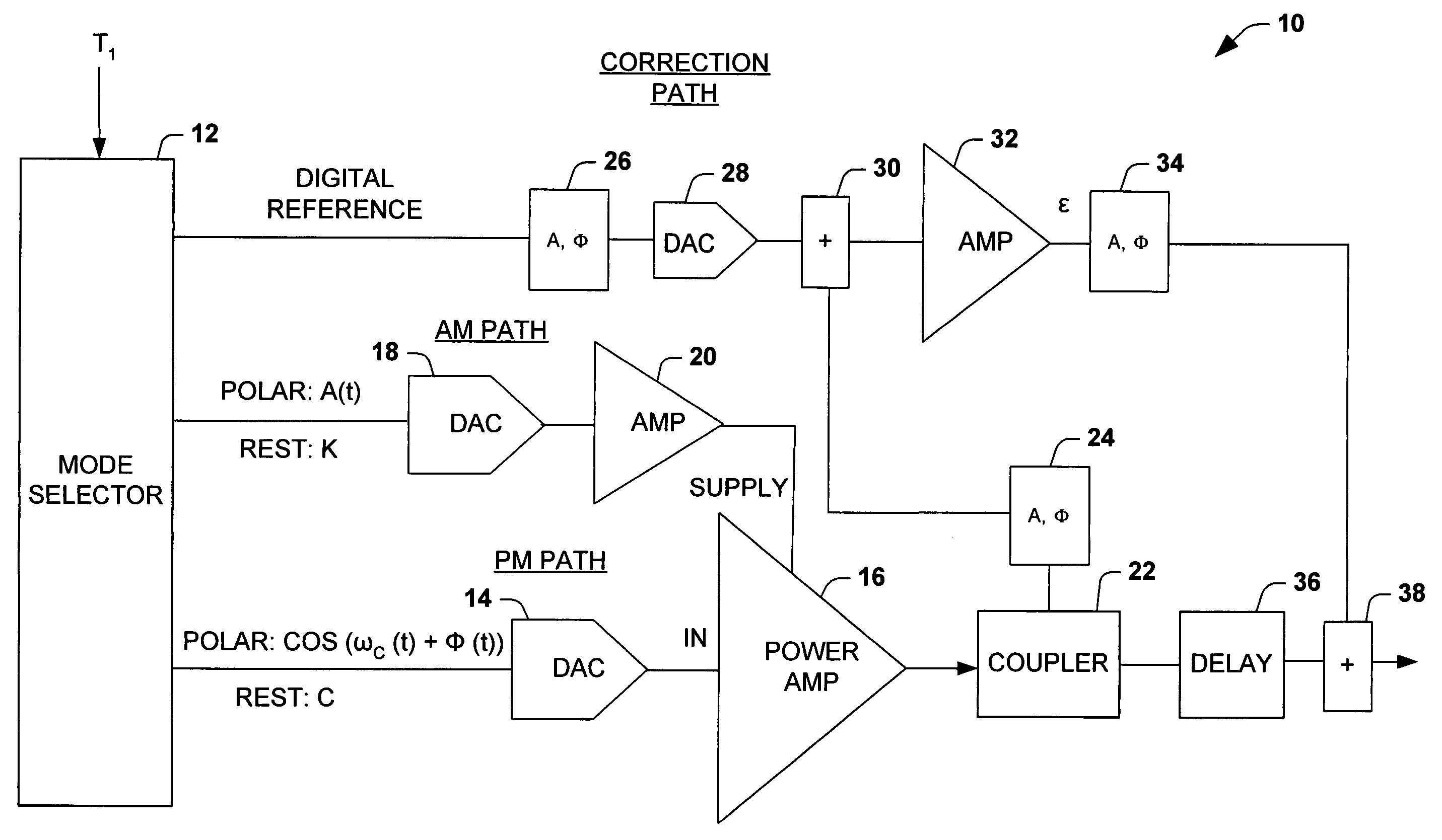
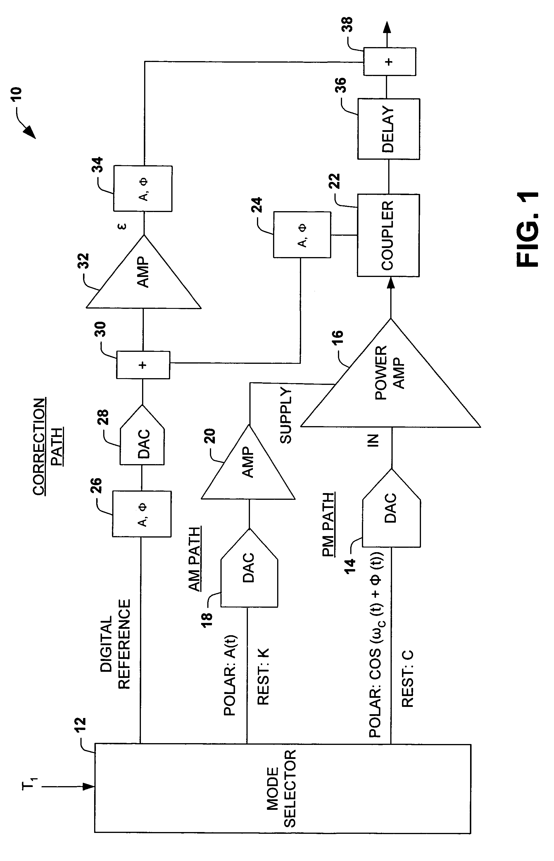
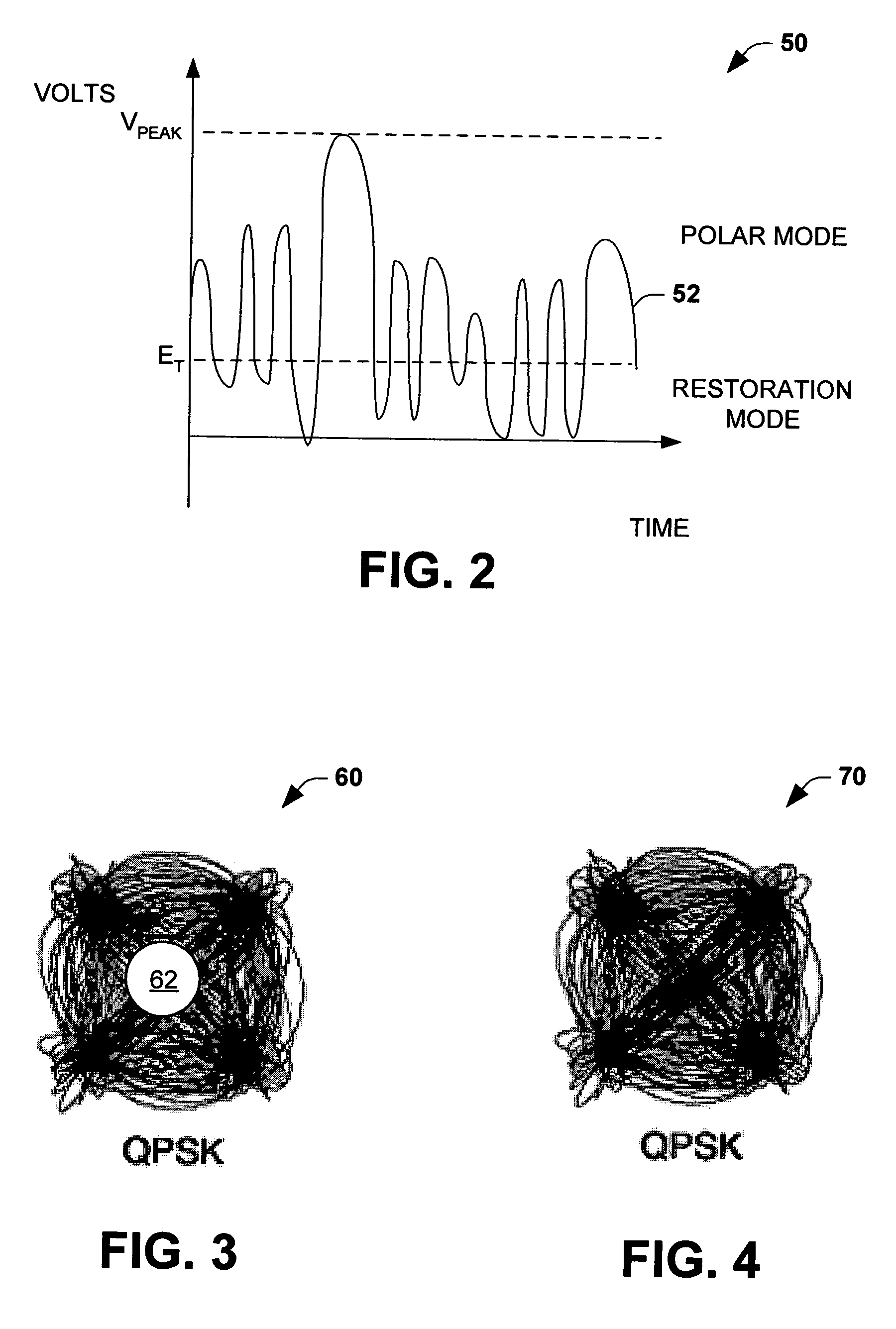
[0018]The present invention relates to an amplifier system that switches modes of operation based on a characteristic of an input signal relative to a threshold level (e.g., envelope amplitude level, digital count representation of signal level, power amplifier power level). The amplifier system operates as a polar amplifier system (i.e., Envelope Elimination and Restoration (EER) technique amplifier) in one mode, and operates as a linear amplifier system via a separate correction path in a restoration mode.

[0019]In one aspect of the present invention, an amplifier system is provided that includes a correction path that corrects for wanted signal distortion and / or OOB emissions in a polar mode, and provides for signal restoration in a signal restoration mode. A mode selector (e.g., a digital component) determines whether polar components (“polar mode”) of the signal are sent to a power amplifier or whether constant or low level (approximately zero level) signals are provided to the ...


PUM


Abstract

An amplifier system is provided that switches between operation in a polar mode and a signal restoration mode based on a characteristic of an input signal relative to a threshold level. The system includes a correction path that mitigates distortion and out-of-band (OOB) emissions in the polar mode and provides at least a substantial portion of the amplified output signal in the signal restoration.

Description

CROSS REFERENCE TO RELATED APPLICATIONS[0001]The present application is related to New Robinson U.S. Patent Application entitled “MULTIPLE POLAR AMPLIFIER ARCHITECTURE”, Filed Nov. 21, 2003, Ser. No. 10 / 719,513, assigned to the same assignee as the present application.TECHNICAL FIELD[0002]The present invention relates generally to electronic devices, and more particularly to a modified polar amplifier architecture.BACKGROUND OF THE INVENTION[0003]Modern transmitters for applications such as cellular, personal, and satellite communications employ digital modulation techniques such as quadrature phase-shift keying (QPSK) in combination with code division multiple access (CDMA) communication. Shaping of the data pulses mitigates out-of-band emissions from occurring into adjacent channels but produces time-varying envelopes. In addition to amplifying individual waveforms with time varying envelopes, many transmitters (especially in base stations) are being configured to amplify multiple...

Claims


Application Information

Patent Timeline
Patent Type & Authority Patents(United States)
IPC IPC(8): H03F1/00H03F1/02H03F1/32H03F3/217H03F3/72
CPCH03F1/02H03F1/0222H03F1/025H03F1/0277H03F1/0288H03F1/3241H03F1/3247H03F3/217H03F3/72H03F1/3223H03F2200/331
Inventor ROBINSON, IANWINTER, FRANK
Owner NORTHROP GRUMMAN SYST CORP
Why Eureka
Try Eureka