Laminated functional wafer for plastic optical elements

a functional wafer and plastic optical element technology, applied in the field of laminated functional wafers, can solve the problems of bleed of the adhesive material and/or the functional layer material, the relative thickness of the coating is not suited for the surface application of a segmented, multi-focal lens, and the inability to meet the requirements of segmented, optical lens segments, etc., to achieve the effect of effectively and efficiently manufacturing plastic lenses and adding functional properties

Active Publication Date: 2006-05-02
HOYA OPTICAL LABS OF AMERICA INC
View PDF28 Cites 88 Cited by
  • Summary
  • Abstract
  • Description
  • Claims
  • Application Information

AI Technical Summary

Benefits of technology

[0018]The present invention illustrates an improved laminate wafer for adding functional properties to plastic lenses. The wafer is especially useful for effectively and efficiently manufacturing plastic lenses through an insert injection molding process. The laminate wafer comprises at least one functional layer and at least one transparent resin sheet....

Problems solved by technology

This relatively thick coating is not suited for application on the surface of a segmented, multi-focal lens.
An unacceptable segment line and coating thickness nonuniformity around the segment line are just a few of the major drawbacks of the technique.
One of the problems associated with conventional wafers in the manufacture of polarized or photochromic lenses by insert injection molding is the bleeding of the adhesive material and/or the functional layer material.
Often bleeding occurs from the deformation of the photochromic layer under the high temperature and pressu...

Method used


Image

  • Laminated functional wafer for plastic optical elements
  • Laminated functional wafer for plastic optical elements
  • Laminated functional wafer for plastic optical elements

Examples


example 1

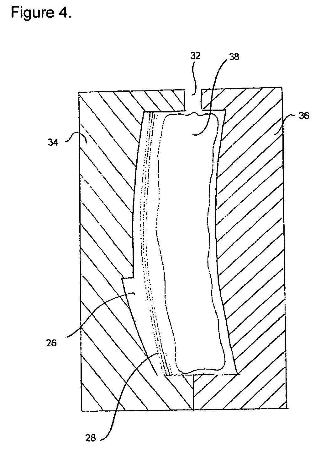
[0089]A photochromic polyurethane laminate having two 0.3 mm thick polycarbonate sheets bonded to a 102 μm cross-linked polyurethane layer, which contains about 1.2% of a gray photochromic compound, was made by Mitsubishi Gas Chemicals (Tokyo, Japan). The laminate was cut into 76 mm diameter wafers, which in turn were spherically formed into 5.7 diopter wafers. The back (concave side) polycarbonate sheet and the photochromic layer were trimmed off from the edge by 2 mm with a Horizon II bevel edger (National Optronics, Charlottesville, Va.) equipped with a rotary carbide steel blade. The resulted wafers were used to make a semi-finished 6-base flat top bi-focal lenses. The front (convex side) polycarbonate sheet faces the concave mold cavity. After the insert injection molding process with common molding parameters, the finished lens has an acceptable segment line. No polyurethane bleeding from the wafer is observed. The mold cavity and surrounding are free of material leftover, and...

example 2

[0090]A 20% polyurethane solution in tetrahydrofuran was obtained from a thermoplastic polyurethane CLC-93A (Thermedics Polymers, Boston, Mass.). To the solution were also dissolved 3.0% of a gray photochromic dye, 2.0% of Tinuvin® 144, and 2.0% of Tinuvine® 765. The solution was cast with a doctor blade on a silicone coated polyester release liner. The cast film was dried at 60° C. for 10 minutes on a hot plate and then 100° C. for another 30 minutes in a hot air dryer.

[0091]A 380 μm thick sheet of polycarbonate from GE (New York, N.Y.) was laminated to the dried film on the liner at ambient temperature. The obtained laminate has a liner on the top, a polyurethane photochromic layer in the middle, and a polycarbonate sheet with masking on the bottom. Next, a 74 mm diameter cutting die was used to kiss-cut the laminate from the liner side on to the polycarbonate sheet to define the size of the photochromic layer. After the liner and un-needed polyurethane film were removed, another ...

example 3

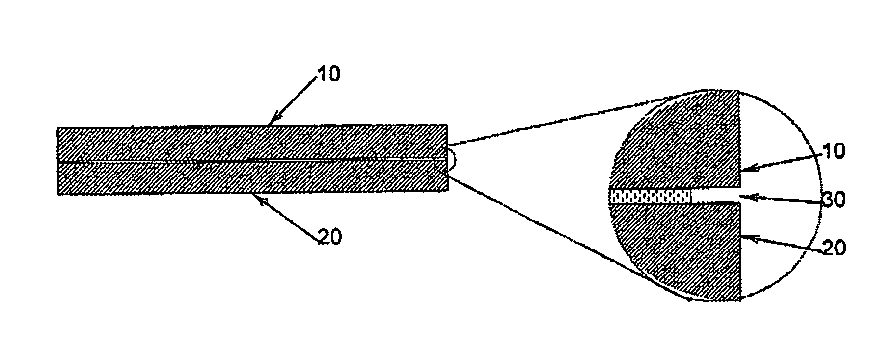
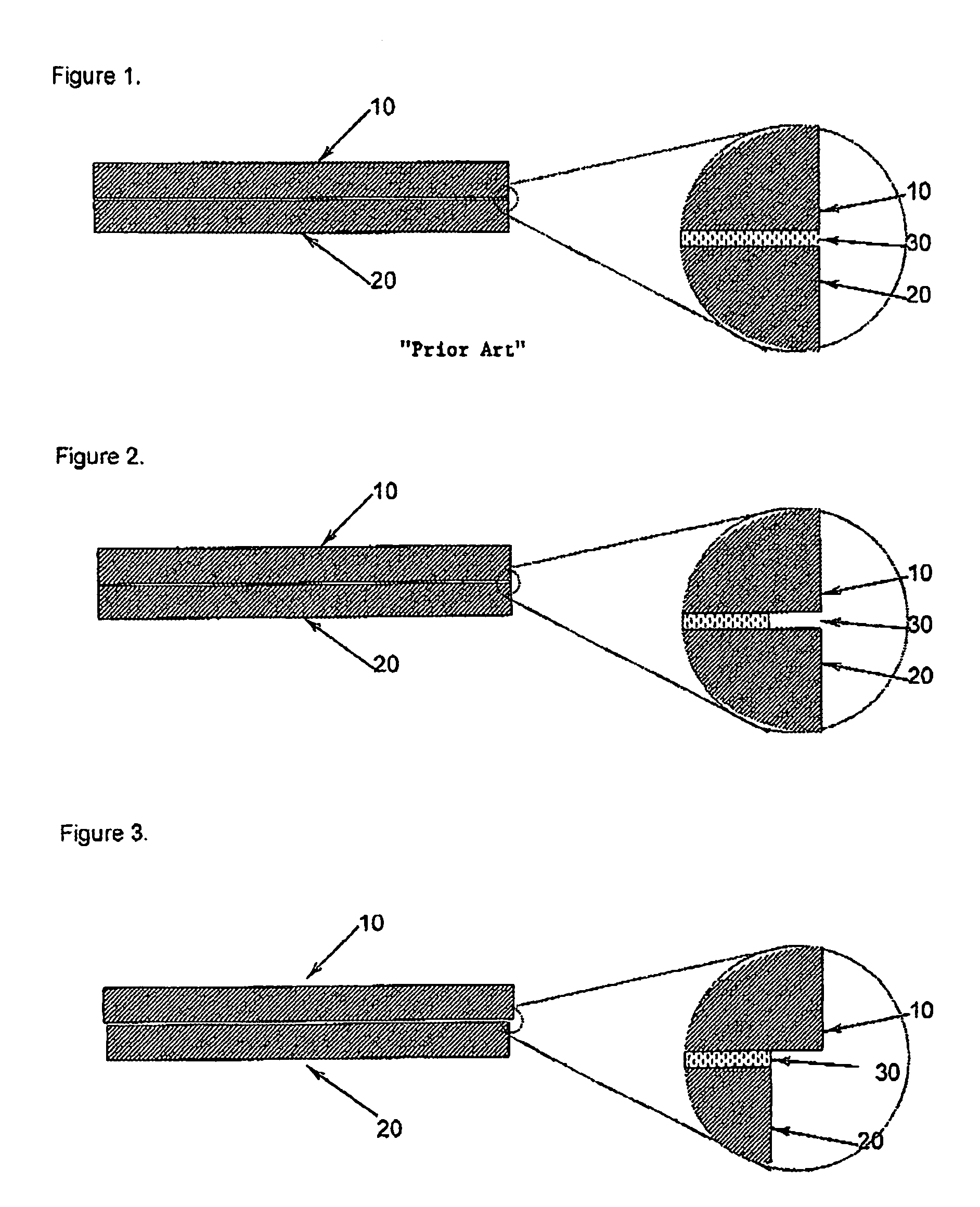
[0093]The procedure of Example 2 was followed, except the kiss-cut went through the first polycarbonate sheet and stopped at its masking film. The wafer so obtained had a polyurethane layer of 50 μm thick, and its back polycarbonate sheet and the photochromic layer were 1 mm smaller than the front polycarbonate sheet from the edge. It was used to make a 6-base semi finished flattop bi-focal lens without forming into a spherical shape. After the insert injection molding process with common molding parameters, the finished lens had an acceptable thin, sharp, crisp segment line. No polyurethane bleeding from the laminate was observed.


PUM

PropertyMeasurementUnit
Lengthaaaaaaaaaa
Lengthaaaaaaaaaa
Diameteraaaaaaaaaa

Abstract

A functional wafer of the present invention is disclosed to solve manufacturing difficulties involved in the production of optical elements such as polycarbonate ophthalmic lenses. The functional wafer may include a front layer, a functional layer, and a back layer, whereas the front layer and the back layer are bonded to the functional layer with or without additional adhesive. Said functional layer is smaller than at least the front layer by about 0.5 mm to 5 mm along the perimeter edge. A functional wafer of this construction can be conveniently and effectively incorporated into a lens through an insert injection molding process, in which said back layer will be in contact with the lens material.

Description

CROSS REFERENCE TO RELATED APPLICATIONS[0001]This application claims the benefit of priority from U.S. Provisional Application Ser. No. 60 / 416,224 filed on Oct. 04, 2002, the entire contents of which are incorporated by reference.BACKGROUND OF THE INVENTION[0002]1. Field of the Invention[0003]The present invention generally relates to laminated wafers and to methods of making laminated wafers. The invention particularly relates to laminated wafers that provide added functions to optical elements. The invention more particularly relates to laminated functional wafers which are incorporated into optical elements using insert injection molding and to methods of making such laminated functional wafers.[0004]2. Description of the Related Art[0005]Plastic ophthalmic lenses made from materials such as polycarbonate and CR-39, have become popular due to their low cost and light weight over glass lenses. Polycarbonate lenses have superior impact resistance compared to CR-39 lenses, and are p...

Claims


Application Information

Patent Timeline
IPC IPC(8): G02C7/10B29C45/14B29D11/00G02C7/12
CPCB29C45/14811B29C45/14836B29D11/0073G02C7/12G02C7/102B29C2045/14901G02C2202/16B29L2011/00B29K2029/04
Inventor BOULINEAU, MICHAEL S.WOELFLE, ERIC J.QIN, XUZHISUGIMURA, HIDEYOHARRIS, DEREK
Owner HOYA OPTICAL LABS OF AMERICA INC
Why Eureka
Try Eureka