
Method and system for reducing Raman gain tilt error

a technology of raman gain and error, applied in the field of optical communication systems, can solve the problems of raman tilt, or effect, degraded wavelength division multiplexed (wdm) signals, particularly troublesome raman tilt, etc., and achieve the effect of reducing gain error

Active Publication Date: 2006-05-02
LUCENT TECH INC
View PDF6 Cites 29 Cited by
  • Summary
  • Abstract
  • Description
  • Claims
  • Application Information

AI Technical Summary

Benefits of technology

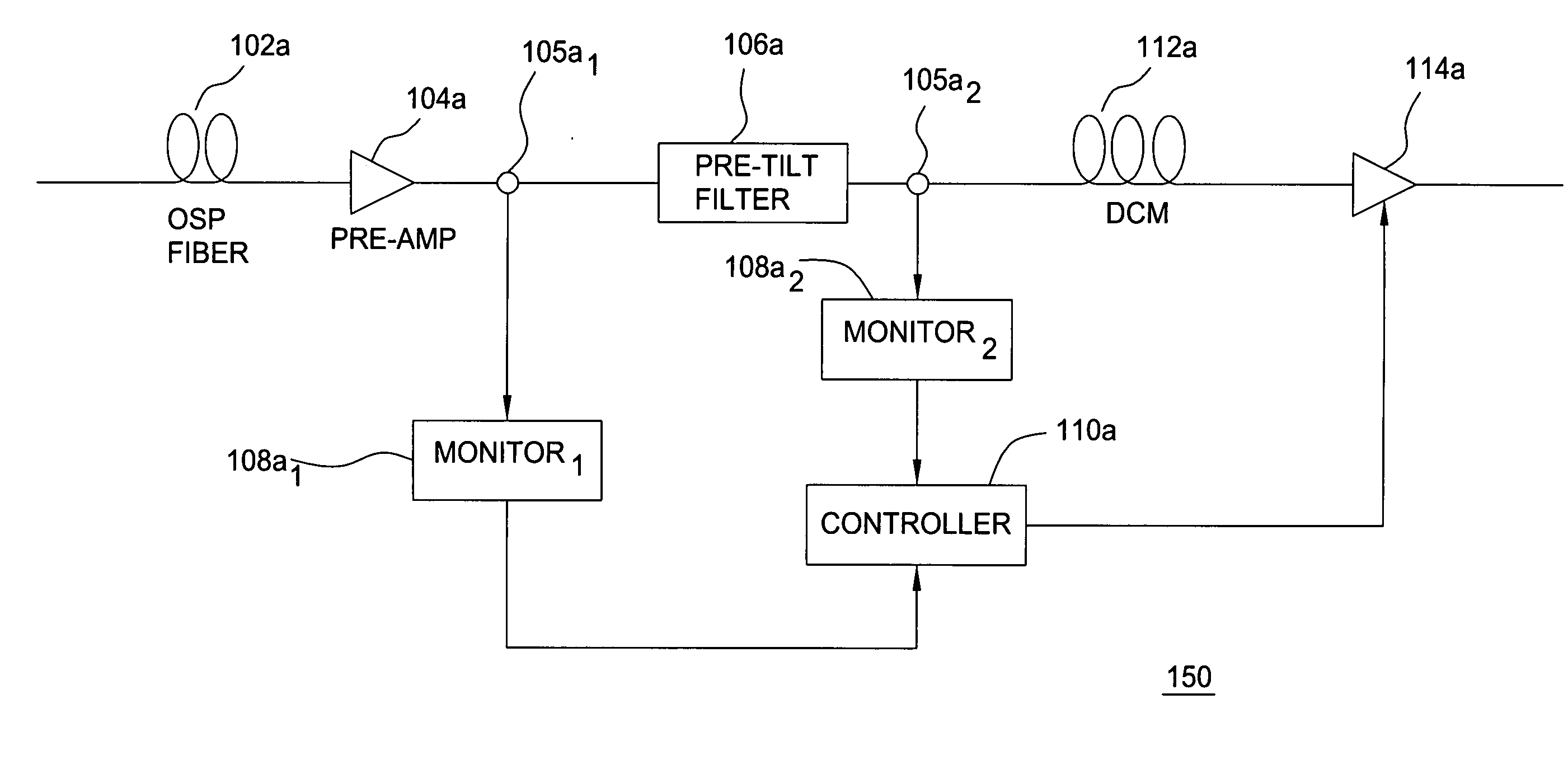
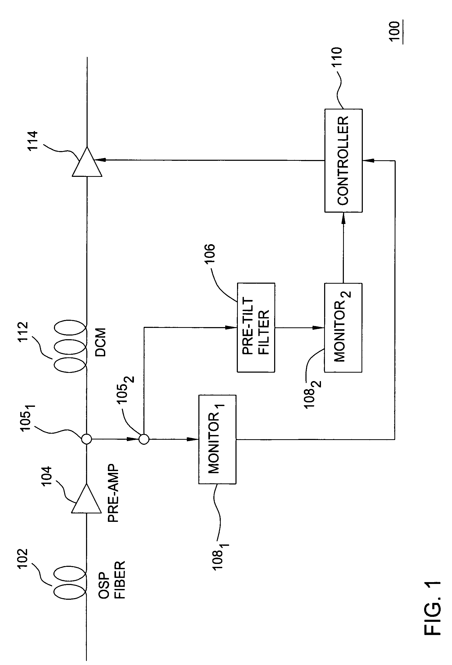
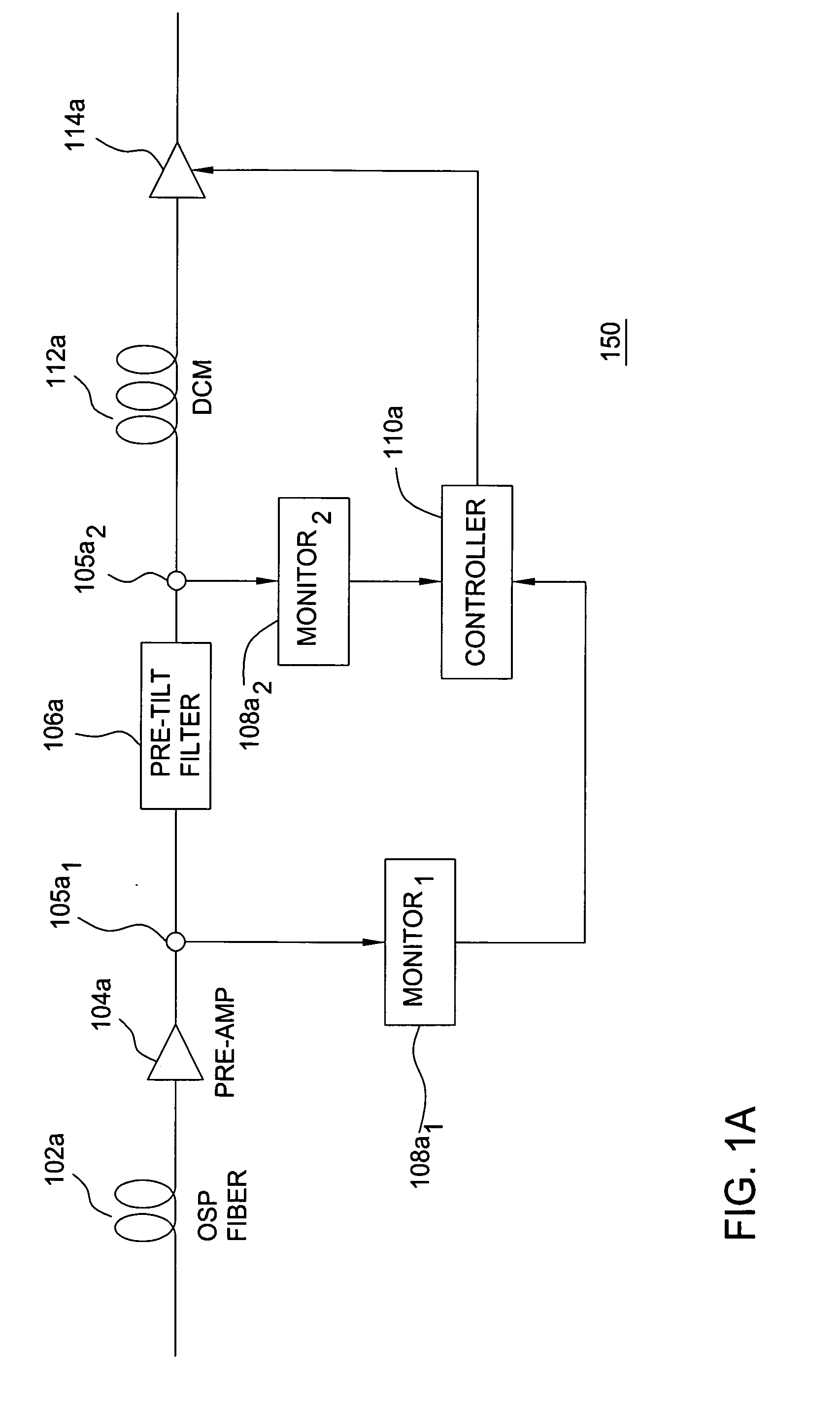
"The present invention provides a method and system for reducing gain error in an optical communication system due to Raman gain tilt. This is achieved by determining the spectral profile of the input WDM optical signal and filtering it to produce a filtered WDM optical signal with a different spectral profile. The average loss between the input WDM optical signal and the filtered WDM optical signal is determined, and if there is a variation in the average loss, the gain parameter of the optical communication system is adjusted to maintain the average power of each optical channel present in the WDM optical signal constant. This results in a more stable optical signal transmission and improved system performance."

Problems solved by technology

Stimulated Raman Scattering (SRS) is an important non-linear effect in fibers that can be used to build Raman amplifiers, but that also degrades Wavelength Division Multiplexed (WDM) signals due to channel-to-channel cross talk and spectral distortion (gain tilt).
The Raman tilt, or effect, becomes particularly troublesome when an appreciable level of optical power distributed over a certain range of wavelengths is pumped into an optical fiber.
The Raman tilt thus degrades the Signal-to-Noise Ratio (SNR) of the signals in the lower wavelength channels and thus seriously degrades their performance.

Method used


Image

  • Method and system for reducing Raman gain tilt error
  • Method and system for reducing Raman gain tilt error
  • Method and system for reducing Raman gain tilt error

Examples


Embodiment Construction

[0021]Although the concepts of the present invention are being illustrated with respect to an optical communication system comprising specific components, such as an erbium-doped fiber amplifier, the concepts of the present invention may be advantageously applied in substantially any optical communication system for the reduction of gain error due to Raman gain tilt during transient events.

[0022]Prior art optical communication systems propose various methods and systems for correcting for Raman tilt due to Raman Scattering by tilting the gain of an included optical amplifier in the opposite direction as the Raman tilt. Such a system is described in U.S. Pat. No. 6,456,0427 entitled “Systems and Methods For Reducing A Signal Spectrum Tilt”, issued Sep. 24, 2002, which is herein incorporated by reference in its entirety. In such systems at least one of a source, a receiver, and a fiber is connected with an amplifier that is configured to produce a gain spectrum with a tilt that has an...


PUM


Abstract

A method and system in accordance with the present invention greatly reduces the gain error due to Raman gain tilt for individual channels in an optical communication system during a transient event by determining a shift in average power (and thus wavelength) and using the determined shift to alter the average gain in the optical communication system. In various embodiments of the present invention, the average gain of the optical communication system is altered by altering the average gain of an amplifier in the optical communication system. In alternate embodiments of the present invention having an in-line optical filter, the average gain of the optical communication system may be altered by altering the filtering of the optical channels in the optical communication system.

Description

CROSS-REFERENCE TO RELATED APPLICATIONS[0001]This patent application is related to U.S. Pat. No. 6,275,313 B1, issued Aug. 14, 2001, which is herein incorporated by reference in its entirety.FIELD OF THE INVENTION[0002]This invention relates to optical communication systems and, more particularly, to a method and system for reducing Raman gain tilt error in optical communication systems.BACKGROUND OF THE INVENTION[0003]An optical transmission system has to contend with a number of different optical fiber nonlinearities, one of which is commonly referred to as Raman tilt introduced by stimulated Raman scattering (SRS). Stimulated Raman Scattering (SRS) is an important non-linear effect in fibers that can be used to build Raman amplifiers, but that also degrades Wavelength Division Multiplexed (WDM) signals due to channel-to-channel cross talk and spectral distortion (gain tilt). The Raman tilt is defined (in dB) as the difference between the power (in dB) of the longest wavelength ch...

Claims


Application Information

Patent Timeline
Patent Type & Authority Patents(United States)
IPC IPC(8): H04B10/12H04B10/17H04J14/02
CPCH04B10/2916H04J14/0221H04B10/2942H04J14/02216
Inventor DENKIN, NATHAN MYRONSPECTOR, MAGALY
Owner LUCENT TECH INC
Learn More