Low power band-gap current reference

a low-power, band-gap current technology, applied in the field of integrated circuits, can solve the problems of imperfect cmos integrated circuits, inability to provide reliable band-gap voltage reference,

Inactive Publication Date: 2006-05-02
AVAGO TECH WIRELESS IP SINGAPORE PTE
View PDF3 Cites 4 Cited by
  • Summary
  • Abstract
  • Description
  • Claims
  • Application Information

AI Technical Summary

Benefits of technology

[0009]A low power supply ha nd-gap current reference of the present invention substantially meets these needs and others. In one embodiment, a low power supply band-gap current reference includes a 1st P-N Junction device, a 2nd P-N junction device, a 1st current source, a 2nd current source, a 1st resistor, a 2nd resistor, a 3rd resistor, an operational amplifier, and a current mirror. The 1st and 2nd P-N junction devices may be diodes, bipolar transistors, and/or field effect transistors operable to emulate bipolar transistors, are operably coupled to the 1st and 2nd current sources, respectively. The 2nd P-N junction device is a larger device than the 1st P-N junction device. The 1st resistor is operably coupled in parallel with the 1st P-N junction device and t

Problems solved by technology

Of these processes, CMOS is the most popular due to its flexibility to support various circuit topologies, its circuit density (i.e. amount of transistors per die area), and its cost.
CMOS integrated circuits, however, are not perfect.
Such a restriction presents a significant probl

Method used


Image

  • Low power band-gap current reference
  • Low power band-gap current reference
  • Low power band-gap current reference

Examples


Embodiment Construction

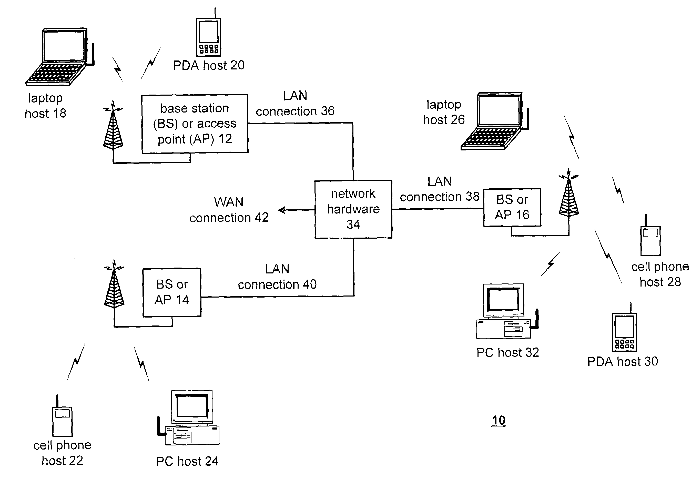
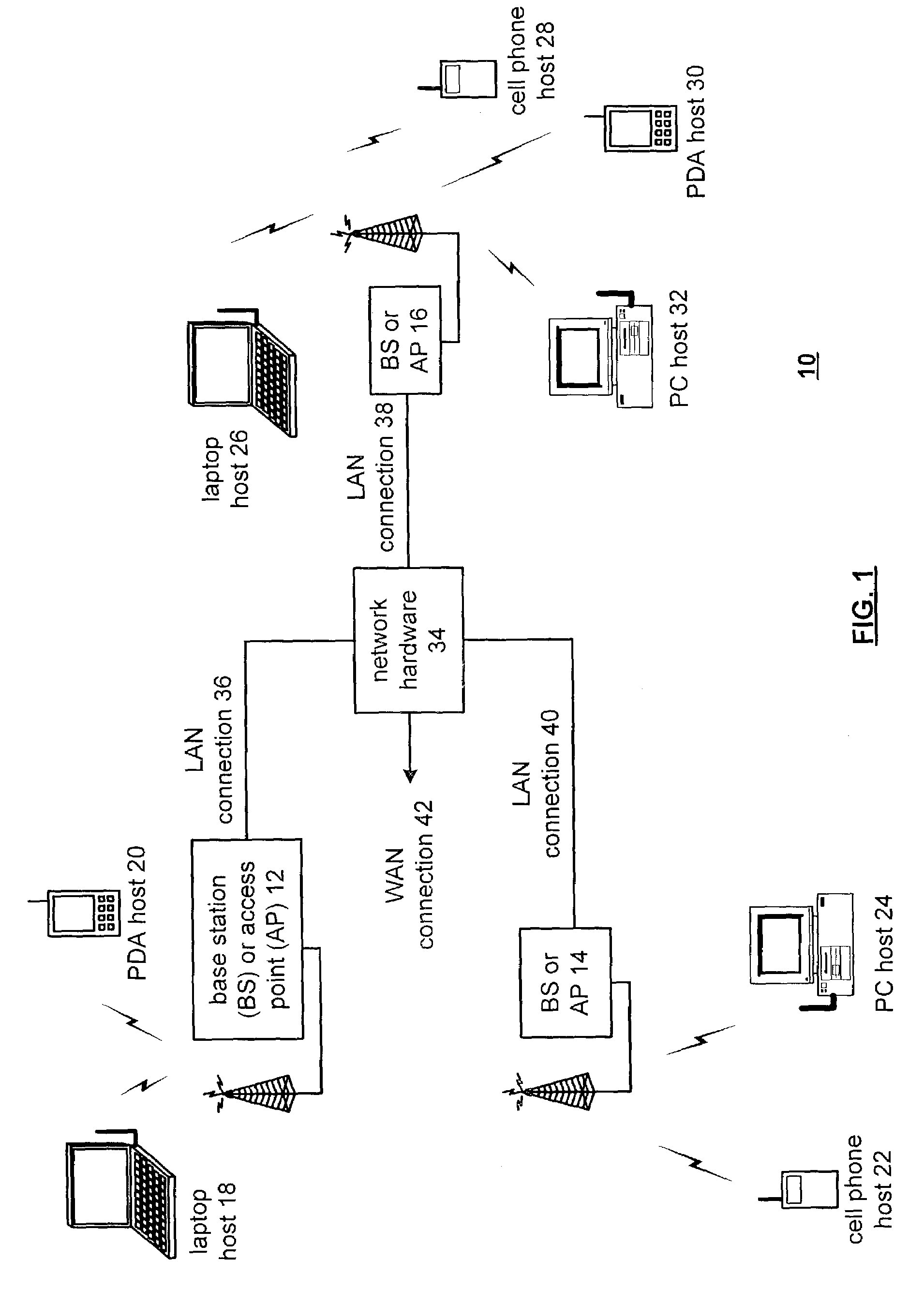
[0018]FIG. 1 is a schematic block diagram illustrating a communication system 10 that includes a plurality of base stations and / or access points 12–16, a plurality of wireless communication devices 18–32 and a network hardware component 34. The wireless communication devices 18–32 may be laptop host computers 18 and 26, personal digital assistant hosts 20 and 30, personal computer hosts 24 and 32 and / or cellular telephone hosts 22 and 28. The details of the wireless communication devices will be described in greater detail with reference to FIG. 2.

[0019]The base stations or access points 12–16 are operably coupled to the network hardware 34 via local area network connections 36, 38 and 40. The network hardware 34, which may be a router, switch, bridge, modem, system controller, et cetera provides a wide area network connection 42 for the communication system 10. Each of the base stations or access points 12–16 has an associated antenna or antenna array to communicate with the wirele...


PUM


Abstract

A low power supply band-gap current reference includes a 1st P-N junction device, a 2nd and P-N junction device, a 1st current source, a 2nd current source, a 1st resistor, a 2nd resistor, a 3rd resistor, an operational amplifier, and a current mirror. The 1st and 2nd P-N junction devices are operably coupled to the 1st and 2nd current sources, respectively. The 2nd P-N junction device is a larger device than the 1st P-N junction device. The 2nd resistor is operably coupled in parallel with the 1st P-N junction device and the 2nd resistor is coupled in series with the 2nd P-N junction device. The 3rd resistor is coupled in parallel with the series combination of the 2nd resistor and 2nd P-N junction device. The operational amplifier is coupled to control the 1st and 2nd current sources based on the voltage imposed across the 1st and 2nd resistors. The current mirror is operably coupled to mirror the current of the 1st and/or 2nd current source to provide a band-gap reference current.

Description

BACKGROUND OF THE INVENTIONTechnical Field of the Invention[0001]This invention relates generally to integrated circuits and more particularly to band-gap references used in such integrated circuits.DESCRIPTION OF RELATED ART[0002]Integrated circuits are used in an abundance of electronic devices ranging, for example, from handheld games to computers to communication systems to home appliances and beyond. Integrated circuits can be manufactured using a variety of processes including bipolar, CMOS, gallium arsenide, and silicon germanium. Of these processes, CMOS is the most popular due to its flexibility to support various circuit topologies, its circuit density (i.e. amount of transistors per die area), and its cost. CMOS integrated circuits, however, are not perfect. For instance, the performance of the components fabricated utilizing a CMOS process varies over temperature and also varies from integrated circuit to, integrated circuit. Multiple techniques have been developed to co...

Claims


Application Information

Patent Timeline
IPC IPC(8): H04B1/28G05F3/30
CPCG05F3/30
Inventor PAN, MENG-AN MICHAEL
Owner AVAGO TECH WIRELESS IP SINGAPORE PTE
Why Eureka
Try Eureka