Dynamic upstream attenuation for ingress noise reduction

Active Publication Date: 2006-05-02
GOOGLE TECH HLDG LLC
View PDF14 Cites 109 Cited by
  • Summary
  • Abstract
  • Description
  • Claims
  • Application Information

AI Technical Summary

Benefits of technology

[0006]The need remaining in the art is addressed by the present invention, which relates to a hybrid fiber cable (HFC) communication system and, more particularly, to an arrangement for reducing the presence of ingress noise in the upstream signal path from a subscriber location to a cable head-end (HE) or hub location.

Problems solved by technology

One technical challenge is to maintain adequate network integrity for signals being transmitted in the return path so that the information in these signals is not contaminated and does not either require retransmission (if data traffic), or is defined as “dropped” (if voice traffic).
For example, two-way dispatch services, amateur radio transmission,

Method used


Image

  • Dynamic upstream attenuation for ingress noise reduction
  • Dynamic upstream attenuation for ingress noise reduction
  • Dynamic upstream attenuation for ingress noise reduction

Examples


Example

EXAMPLE

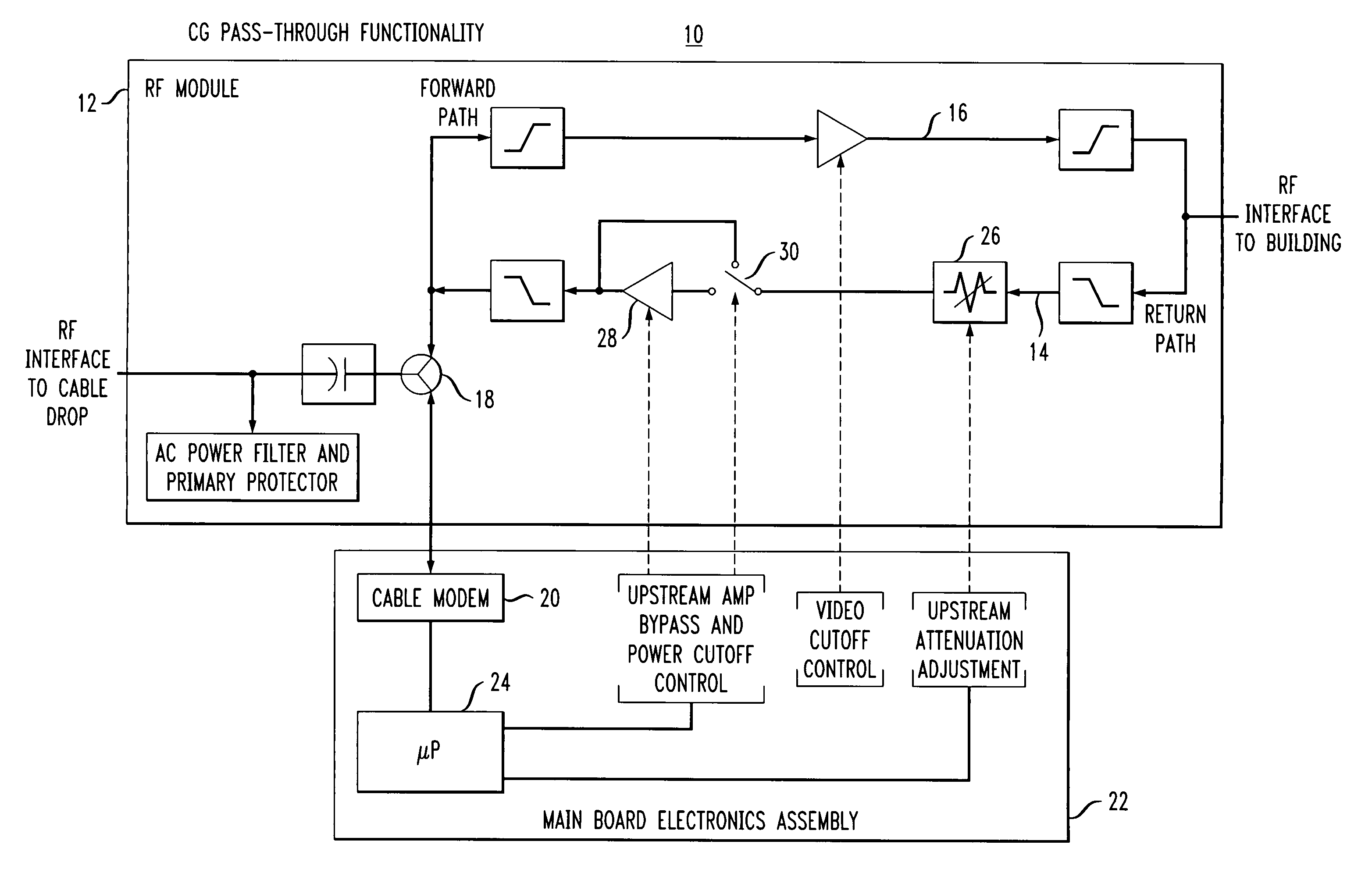
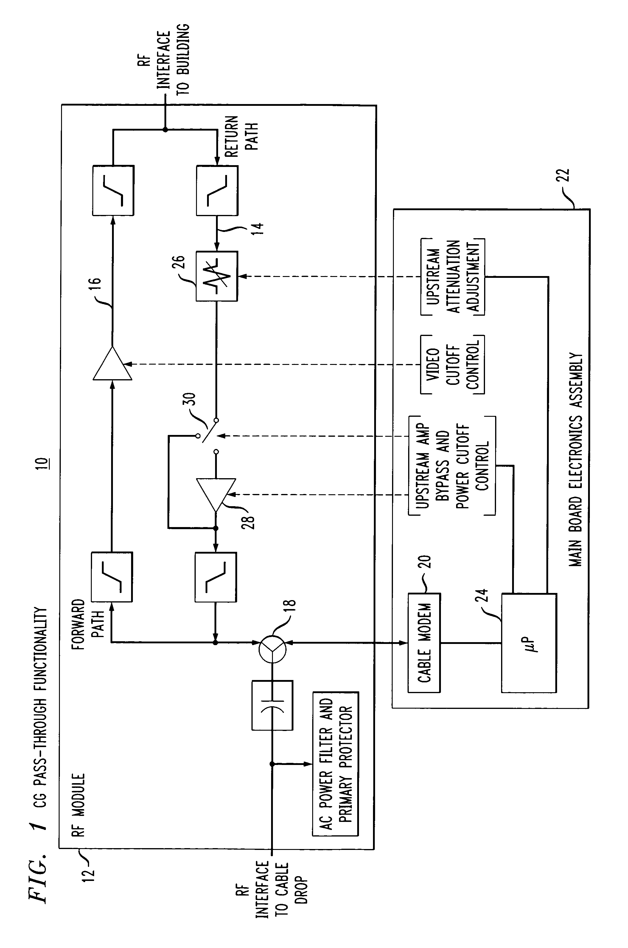
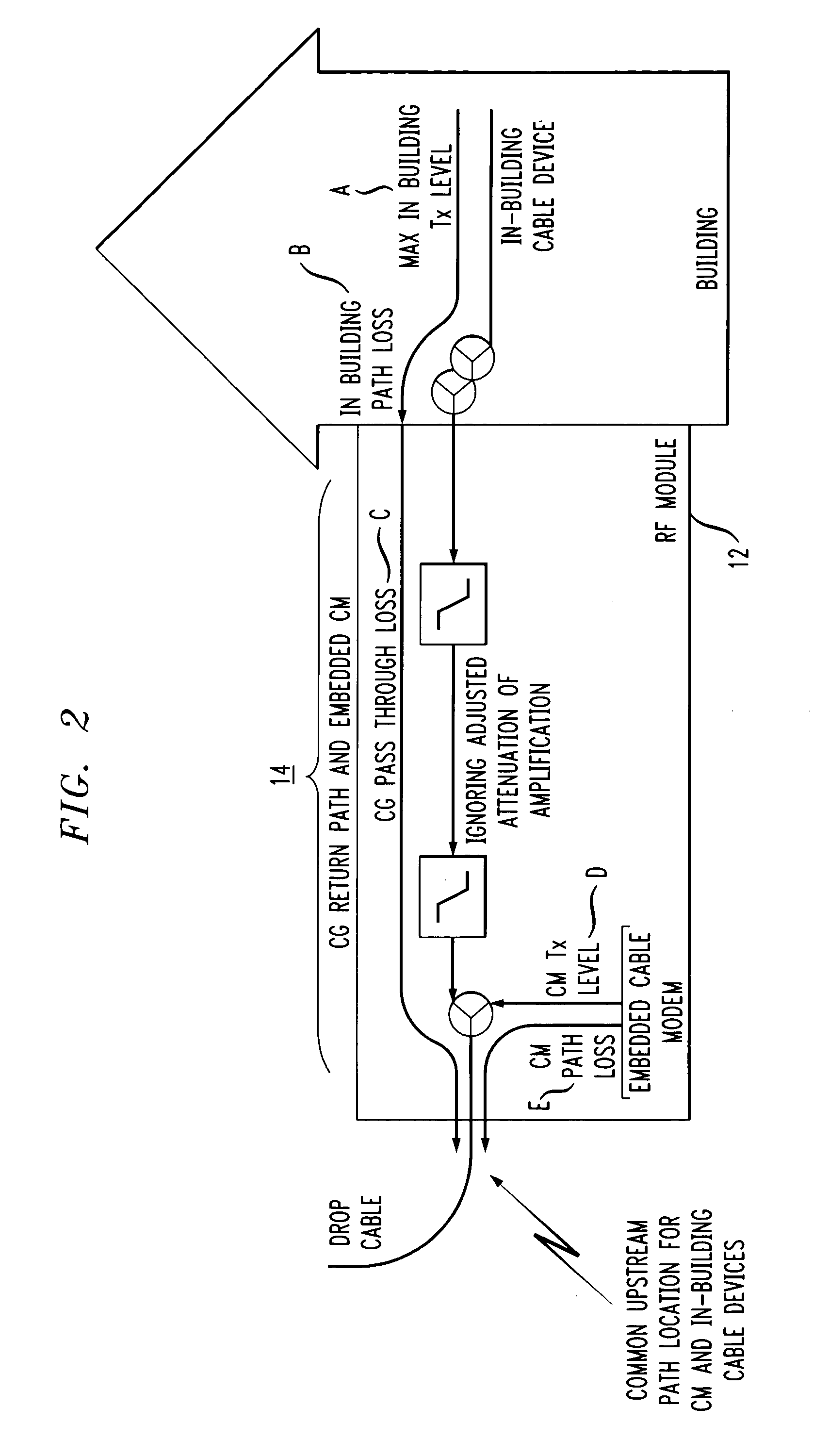
[0031]The following example is useful in understanding the application of the ingress noise reduction technique of the present invention. In particular, consider the following configured parameters for USLossCalc:[0032]MaxInBuildingTxLevel=58 dBmV for the maximum DOCSIS 1.1 transmit level for QPSK modulation. This could be associated with an individual cable modem, a video set-top-box, or telephony Media Terminal Adapter (MTA) with embedded CM. Alternatively, the value could be smaller, associated with a narrowband video return path for a set-top-box that does not utilize an embedded CM. The choice of cable device associated with MaxInBuildingTxLevel will influence the choice of InBuildingTxBW, as shown below.[0033]InBuildingPathLoss=8 dB for two cable splitters in the home[0034]CGPassthroughLoss=5 dB for a single splitter and dual duplex filter losses between the CG's RF interface at the building and cable drop[0035]CMPathLoss=4 dB for a single splitter between the CG's CM i...


PUM


Abstract

A dynamic arrangement for reducing the presence of ingress noise in the upstream signal path of a two-way cable system utilizes a variable attenuation element and amplifier disposed along the upstream signal path. The amplifier includes a bypass switch so that the amplifier may be switched in to or out of the upstream path. A signal processor associated with the communications gateway functions to calculate the upstream loss present at the gateway and control the operation of the attenuation element, amplifier and bypass switch accordingly. Upstream attenuation is selected to be as large as possible, yet still allow in-building cable devices to communicate with their associated head end (HE) receiver equipment, after accounting for maximum transmit limitations.

Description

CROSS-REFERENCE TO RELATED APPLICATION[0001]This application claims the benefit of Provisional Application No. 60 / 336,669 filed Dec. 4, 2001.TECHNICAL FIELD[0002]The present invention relates to a hybrid fiber cable (HFC) communication system and, more particularly, to an arrangement for reducing the presence of ingress noise in the upstream signal path from a subscriber location to a cable head-end (HE) or hub location.BACKGROUND OF THE INVENTION[0003]Modern cable systems utilize a hybrid fiber cable (HFC) architecture in which signals are distributed via a fiber optic connection to a node that converts the optical signal to an electrical signal and distributes the signals to residences (subscribers) via a tree and branch coaxial cable distribution network (“plant”) consisting of the coaxial cable, amplifiers and taps. The plant can be made bidirectional through the use of a fiber optic return signal from the node to the head end. A return band, typically from 5–42 MHz, is used to ...

Claims


Application Information

Patent Timeline
IPC IPC(8): H04B7/01H04B1/10H04N7/10
CPCH04N7/102H04B1/109
Inventor STRATER, JAYSTONEBACK, DEANCHANG, KEVIN T.
Owner GOOGLE TECH HLDG LLC
Why Eureka
Try Eureka