
Internal broadcast reception system for mobile phones

a mobile phone and reception system technology, applied in the direction of antennas, pivotable antennas, collapsible antennas, etc., can solve the problems of increasing the weight and size of hand-held devices, undesirable to have an external antenna protruding, and visible obstruction, etc., to achieve easy production, easy to interface with other mechanical and electronic components, and cost-effective

Inactive Publication Date: 2006-05-02
RPX CORP
View PDF11 Cites 13 Cited by
  • Summary
  • Abstract
  • Description
  • Claims
  • Application Information

AI Technical Summary

Benefits of technology

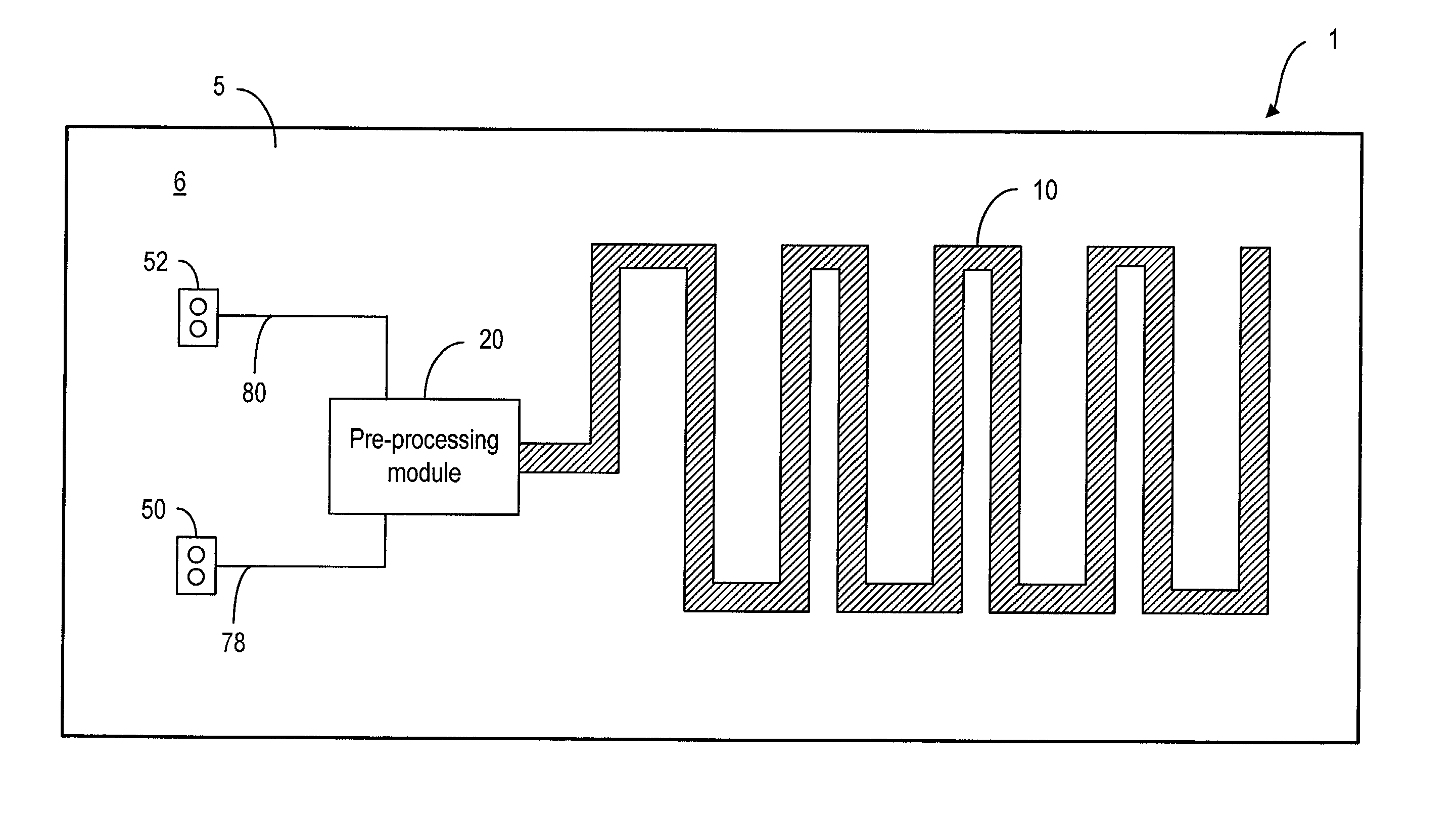
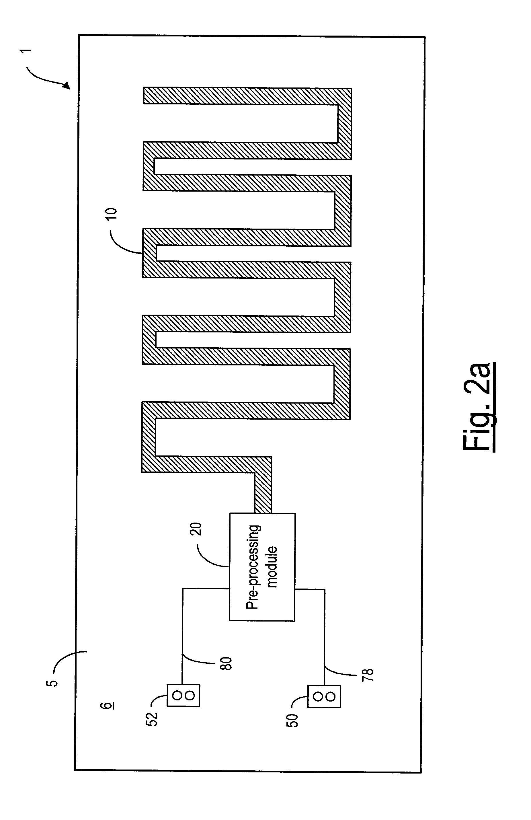
[0004]It is a primary objective of the present invention to provide an internal FM / digital-broadcast reception system for use in a hand-held telecommunication device, such as a mobile phone. The entire reception system can be disposed within the housing of the mobile phone without external parts connecting to the reception system. The reception system is lightweight, cost effective, easy to produce, and can be easily interfaced with other mechanical and electronic components in the mobile phone. The above objective can be achieved by integrating an FM / digital antenna with necessary signal processing electronics on a common substrate, which has a small size to be disposed entirely within the housing of the mobile phone.
[0011]According to the present invention, the electrically conductive element may have a meandering pattern in order to reduce the size of the electrically non-conductive substrate.
[0012]According to the present invention, the electrically conductive element may be wound around the electrically non-conductive substrate so as to reduce the physical size of the electrically conductive element and, therefore, the size of the electrically non-conductive susbstrate.

Problems solved by technology

The major disadvantages of such external antennas are that they are visibly obtrusive and they increase the weight and the size of the hand-held device.
In particular, when a mobile phone is equipped with an FM-broadcast reception system, it is undesirable to have an external antenna protruding out of the phone body, or to require the phone user to use a head-set in order to receive the FM broadcast signals.

Method used


Image

  • Internal broadcast reception system for mobile phones
  • Internal broadcast reception system for mobile phones
  • Internal broadcast reception system for mobile phones

Examples


Embodiment Construction

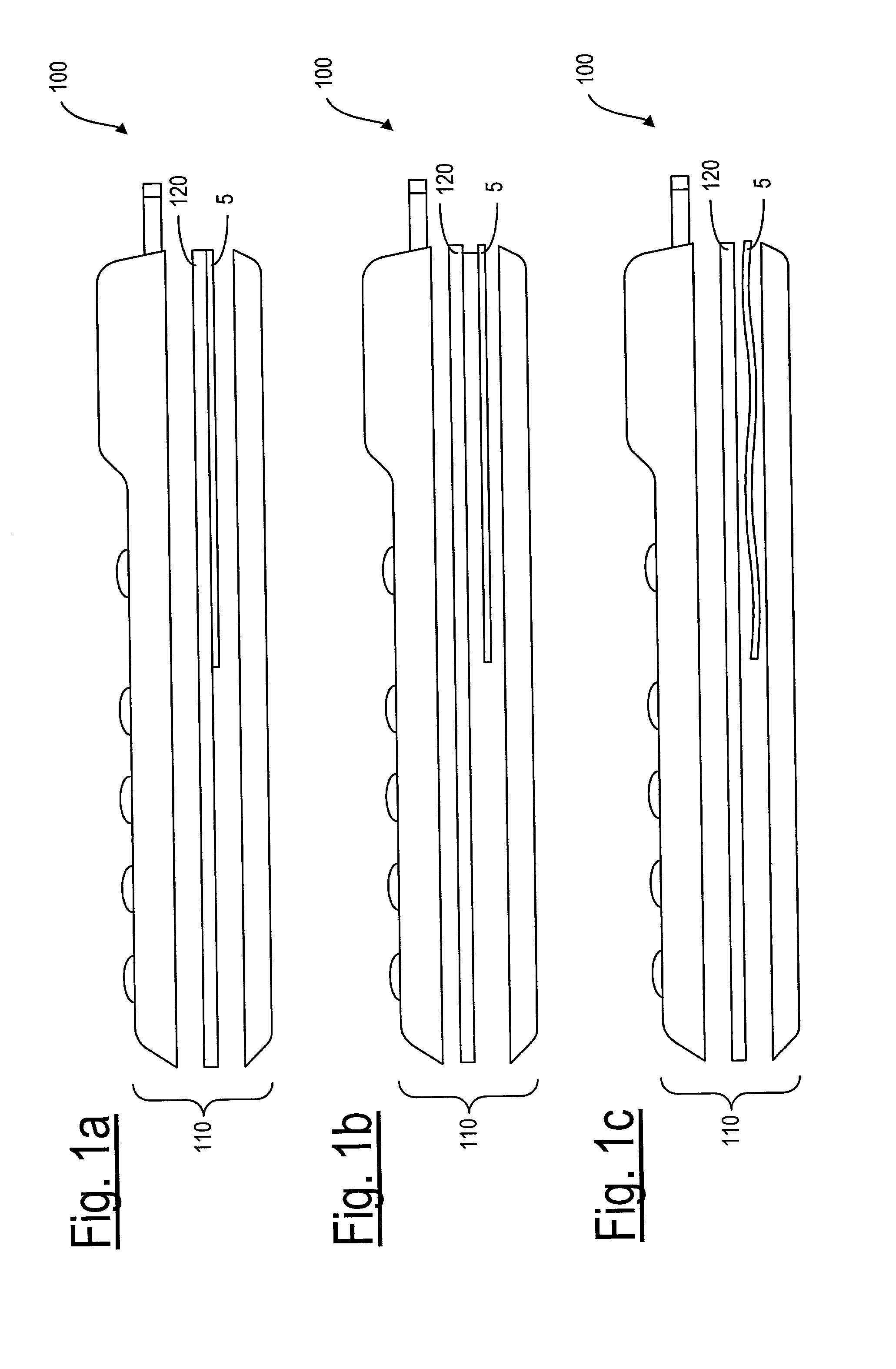
[0040]The basic components of the integrated FM / digital broadcast reception system 1, according to the present invention, include an antenna 10 directly connected to a preprocessing module 20. The antenna 10 and pre-processing module 20 are disposed on a substrate 5, as shown in FIGS. 2a and 2b. The antenna 10 can be printed on the substrate 5 or etched out from a ground plane 60 of a printed circuit board (PCB) or a printed wire board (PWB). As such, the integrated reception system 1 is easy to produce and install in a hand-held telecommunication device such as a mobile phone 100, as shown in FIGS. 1a–1c.

[0041]As shown in FIGS. 1a–1c, the mobile phone 100 has a phone body or housing 110, and a chassis 120 on which some or all electronic telecommunication components are disposed. For example, a microprocessor or ASIC is usually disposed on the chassis 120, along with a display, a SIM card reader, memory, battery and so on. The chassis is not part of the invention. The substrate 5 f...


PUM


Abstract

An integrated reception system for use in a mobile phone for receiving FM / digital broadcast signals. The reception system, which is installed within the phone body, includes a substrate, an antenna having a meandering pattern disposed on the substrate for receiving the broadcast signals, and a pre-processing module disposed on the substrate and connected to the antenna for pre-processing the received signals. The pre-processing module may include a passive filtering network for band-tuning, and an active amplifier for amplifying the received signals from the antenna. The mobile phone has components for converting the received signals into audio signals to produce audio sound.

Description

FIELD OF THE INVENTION[0001]The present invention relates generally to an internal antenna for use in a handheld device such as a mobile phone and, more particularly, to an internal reception system for receiving FM / digital broadcast signals.BACKGROUND OF THE INVENTION[0002]It is known that frequency-modulation (FM) broadcast signals are commonly transmitted with carrier waves in the frequency range of 88–108 MHz. FM broadcasting is also referred to as very high frequency (VHF) radio broadcasting. To receive the FM broadcast signals, a quarter-wave antenna having a length in the order of 85 cm is required. In order to accommodate such a length, hand-held devices usually use external antennas, such as telescope-type antennas and head-set wires for FM broadcast reception. The major disadvantages of such external antennas are that they are visibly obtrusive and they increase the weight and the size of the hand-held device. In particular, when a mobile phone is equipped with an FM-broad...

Claims


Application Information

Patent Timeline
IPC IPC(8): H04M1/00H01Q1/08H01Q1/24H01Q1/36H01Q1/38H01Q23/00
CPCH01Q1/084H01Q1/243H01Q23/00H01Q1/38H01Q1/362
Inventor KOJOLA, ILKKA TARMOTUOMINEN, MIKA JUHANI
Owner RPX CORP
Learn More