
Vehicle suspensions

a suspension and vehicle technology, applied in the direction of resilient suspensions, vehicle springs, transportation items, etc., can solve the problem of less rigidity, and achieve the effect of reducing said resistan

Inactive Publication Date: 2006-05-09
JAGUAR LAND ROVER LTD
View PDF12 Cites 13 Cited by
  • Summary
  • Abstract
  • Description
  • Claims
  • Application Information

AI Technical Summary

Benefits of technology

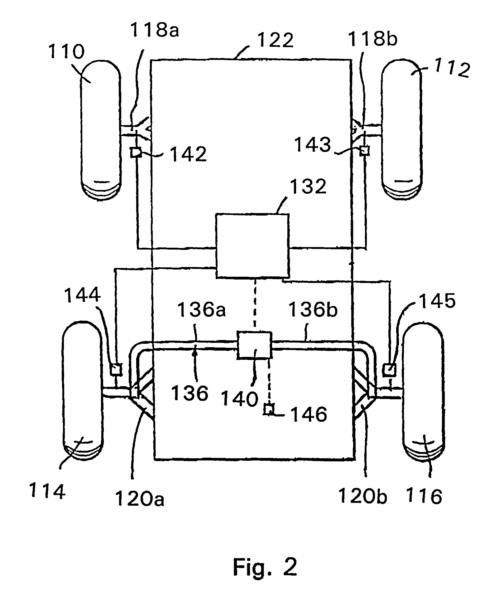
[0011]The present invention provides a vehicle suspension system for connecting at least one pair of wheels to opposite sides of a vehicle body, the system comprising a suspension associated with said at least one pair of wheels and arranged to allow articulation movement of said at least one pair of wheels relative to the body and to provide adjustable resistance to said articulation movement, sensors arranged to measure movement of the suspension, and a controller arranged to monitor said movement and to determine therefrom the level of said articulation movement and to reduce said resistance if said articulation movement reaches a predetermined level.

Problems solved by technology

However this can conflict with the need for firm roll control when the vehicle is traveling at higher speeds on a road, since roll can be considered as articulation of the front and rear axles in the same direction.
The same conflict arises with the use of anti-roll bars which need to be stiff to provide good roll control on road, but much less stiff to allow sufficient articulation off-road.

Method used


Image

  • Vehicle suspensions
  • Vehicle suspensions
  • Vehicle suspensions

Examples


first embodiment

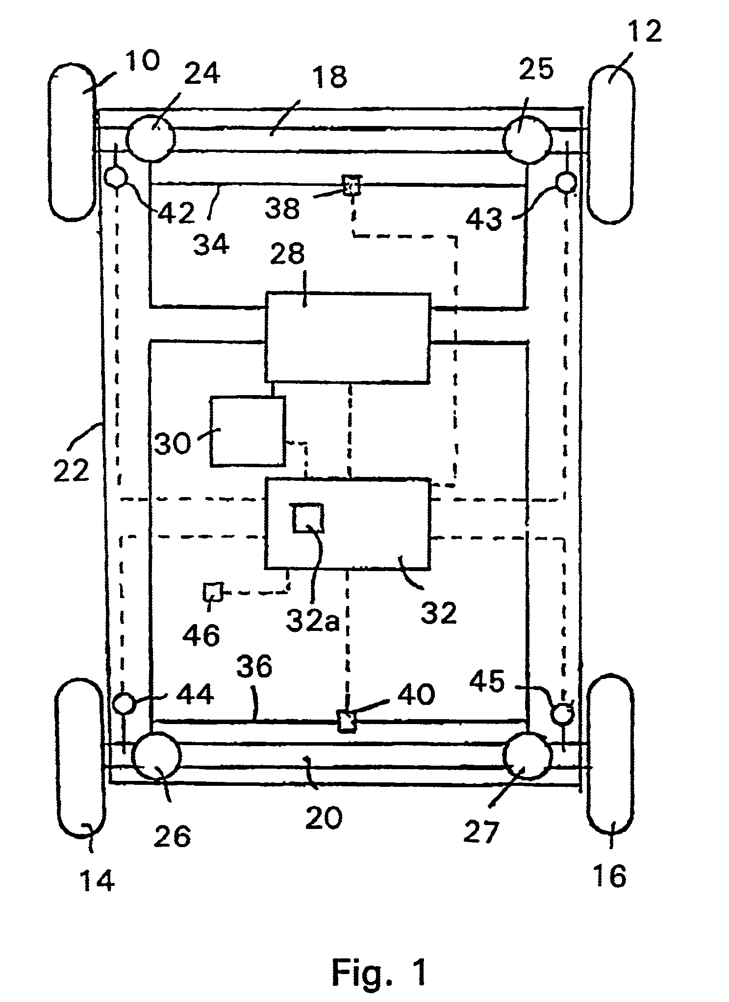
[0054]As mentioned above, the system also needs to deal with situations where the vehicle is driving on a side slope. With the first embodiment, which uses a measure of cross articulation to control the level of resistance to articulation, a side slope will not interfere with the detection of rough terrain. However if the vehicle is travelling on a side slope, opening the cross link valves 38, 40 and thereby reducing the roll stiffness of the vehicle will allow the vehicle body 22 to roll towards the downhill side of the vehicle. This can reduce the lateral stability of the vehicle. Therefore the control unit 32 is arranged to provide a measure of the side slope and, if that measure exceeds a certain threshold or limit, implying that the vehicle is on a side slope of at least a certain steepness or angle, to close one or both of the cross link valves 38, 40, irrespective of the levels of articulation movement being measured, thereby increasing the roll stiffness. The degree of side ...

second embodiment

[0057]In the invention the cross linking valves 38, 40 can each be opened and closed independently of the other, on the basis solely of the level of articulation of the respective axle 18, 20. In this case the two articulation displacements Af and Ar are measured as above and the modulus of each taken and low pass filtered. A running integral Zx for each is then taken of the same form as that of the cross articulation described above, i.e.

[0058]Articulation_level⁢⁢Zx=∫0∞⁢(Articulationx,LPF-X)*k

[0059]where X is a speed dependent offset which increases with vehicle speed and k is a scaling factor, and x is either f for the front articulation or r for the rear articulation. The cross link valve 38, 40 for each axle is then controlled solely on the basis of the running articulation displacement measure Zx for that axle, being opened when it rises above a threshold value, and closed again when it falls below that value.

[0060]This method has the advantage that each axle can be controlled ...


PUM


Abstract

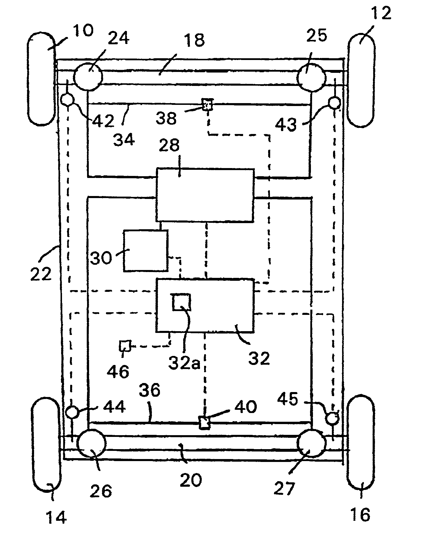
A vehicle air suspension system includes a control unit 32 which is arranged to produce a running measure of the level of cross articulation of the two axles 18, 20 and, if it exceeds a certain level indicating that the vehicle is on rough terrain, to open respective interconnections 34, 36 between the suspension units 24 on opposite ends of each axle so as to reduce the resistance to that articulation. The interconnections are arranged to close when the vehicle speed increases so as to provide roll control.

Description

[0001]This application is a divisional of Ser. No. 09 / 715,284 filed Nov. 17, 2000 now U.S. Pat. No. 6,688,612 which claims priority from Great Britain Application Ser. No. 99 272 95.7 filed Nov. 19, 1999.FIELD OF THE INVENTION[0002]The present invention relates to active and semi-active vehicle suspensions and in particular to such suspensions for off-road vehicles.BACKGROUND OF THE INVENTION[0003]Vehicle suspensions are characterized in various ways, including the stiffness in roll, single axle articulation, and cross articulation. There are two aspects of a suspension which determine how easily the wheels can move in articulation. One is the damping rate of the dampers, and the other is the spring rate of the springs in the suspension. The term stiffness refers to the spring rate. Therefore the articulation stiffness of the front axle of a vehicle is expressed as a force (expressed as a moment or a linear force) per unit of articulation displacement of the front wheels (expressed ...

Claims


Application Information

Patent Timeline
IPC IPC(8): B60R17/02B60G17/015B60G17/052B60G21/055B60G21/10G02B21/00
CPCB60G17/0155G02B21/0076B60G21/0555B60G21/10G02B21/0032B60G17/0523B60G2200/10B60G2200/30B60G2202/135B60G2202/152B60G2202/412B60G2300/07B60G2400/204B60G2400/252B60G2500/203B60G2500/302B60G2600/02B60G2600/70B60G2800/01
Inventor BURDOCK, WILLIAMWILLIAMS, STEPHEN
Owner JAGUAR LAND ROVER LTD
Learn More