
Bioreactor and bioprocessing technique

a bioreactor and bioprocessing technology, applied in the field of bioreactors, can solve the problems of discarding the batch of drugs, wasting resources, and wasting resources, and achieving the effect of reducing the number of batch drugs

Inactive Publication Date: 2006-05-09
HEWLETT PACKARD DEV CO LP
View PDF3 Cites 72 Cited by
  • Summary
  • Abstract
  • Description
  • Claims
  • Application Information

AI Technical Summary

Benefits of technology

[0026]An object of the invention is to solve at least the above problems and/

Problems solved by technology

The sequencing of the human genome has been a mammoth task, however, many have pointed out that this effort pales in comparison to what lies ahead.
During production of the new drug, any deviation from the operating window results in the discarding of that batch of drug.
This is expensive and time-consuming in practice, as this type of research is typically performed in shake flasks (with practically no control of the bioprocess parameters) or in 1- to 100-liter laboratory scale bioreactors (Tholudur, A. et al., Biotechnol. Bioeng. 66: 1–16 (1999)).
However, this approach also requires a significant number of fermentations for establishing process parameters.
Further, currently available laboratory scale bioreactors are expensive and bulky, thus making bioprocess development and optimization inefficient as large numbers of simultaneous experiments cannot be conducted.
However, in small volumes, e.g., 1–2 ml or less, it is difficult, if not impossible, to use standard industrial probes for culture monitoring due to the probes' physical dimensions.
Another problem is that standard Clark-type oxygen probes consume oxygen (Lee, Y. H. and Tsao, G. T., Advances in Biochemical Engineering, Ghose, T. K. et al.
However, their use in bioprocessing is not economically feasible due to the sophisticated and expensive techniques required to manufacture the miniaturized probes.

Method used


Image

  • Bioreactor and bioprocessing technique
  • Bioreactor and bioprocessing technique
  • Bioreactor and bioprocessing technique

Examples


example 1

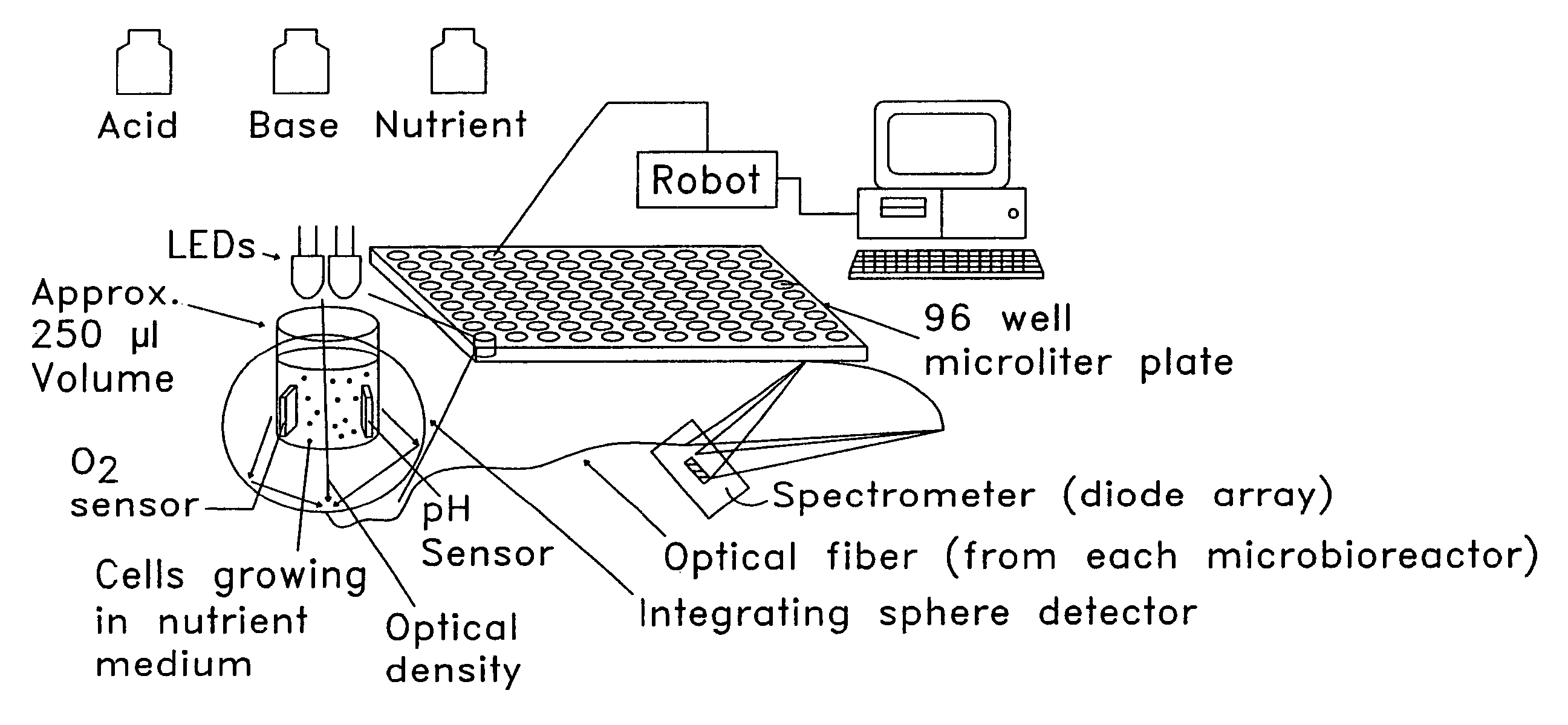
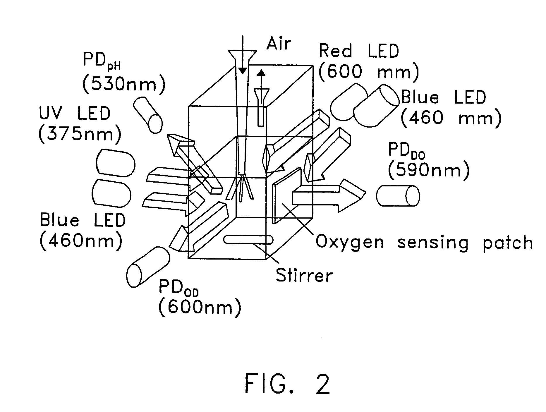
[0116]In this example, the working volume was scaled down to about 2 ml by using a disposable cuvette as the bioreactor. The design of the microbioreactor is presented in FIG. 2. Three parameters, pH, DO and OD, were continuously measured using optical chemical sensors. A test fermentation was performed in the microbioreactor and the results were compared with the results from a fermentation in a standard 1 liter bioreactor.

[0117]The working bioreactor was a disposable polystyrene cuvette, 1×1 cm, with a total volume of 4 ml. To avoid contamination during cultivation, it was equipped with a silicone rubber cap. The cap had an inlet for air delivery and outlet for exhaust air. The inlet and outlet were positioned at the corners of the cuvette to avoid overlapping with the optical path for OD measurements. The inlet was connected to an air sparger, as indicated in FIG. 2, which was fabricated from a 100 μl plastic pipette tip. Three tubes with inner diameters of 0.25 mm were positione...


PUM


Abstract

The inventive bioprocessing system (and technique) relies on non-invasive optical chemical sensing technology wherein an optical excitation source excites an optical chemical sensor. The optical chemical sensor then emits luminescence or absorbs light which is measured by a detector. The luminescence emitted from the chemical sensor or the amount of light absorbed by the chemical sensor is related to the concentration of an analyte, such as oxygen. If the luminescence emitted changes, or if the amount of light absorbed changes, then the concentration of the analyte has changed. Using such a system to measure and adjust multiple parameters at one time allows one to efficiently and cost-effectively determine optimal conditions for a given cell type and / or cell environment, for example. By combining cell cultivation with optical chemical sensing technology, cultivation can be successfully and rapidly performed, controlled and monitored in small volumes in an automated, parallel fashion at less expense than current bioprocess techniques.

Description

[0001]This application claims priority to U.S. Provisional Application Ser. No. 60 / 225,108, filed Aug. 14, 2000, whose entire disclosure is incorporated herein by reference.BACKGROUND OF THE INVENTION[0002]1. Field of the Invention[0003]The present invention pertains to a bioreactor, more particularly, a low volume bioreactor (microbioreactor). Further, the present invention pertains to the use of non-invasive optical chemical sensors to measure multiple parameters in a bioprocessing system.[0004]2. Background of Related Art[0005]Bioprocesses are important in a wide variety of industries such as pharmaceutical, food, ecology and water treatment, as well as to ventures such as the human genome project (Arroyo, M. et al., Biotechnol Prog. 16: 368–371 (2000); Bakoyianis, V. and Koutinas, A. A., Biotechnol Bioeng. 49: 197–203 (1996); Bylund, F. et al., Biotechnol Bioeng. 69: 119–128 (2000); Handa-Corrigan, A. et al., J. Chem. Technol. Biotechnol. 71: 51–56 (1998); López-López, A. et al....

Claims


Application Information

Patent Timeline
IPC IPC(8): C12M1/34C12M1/36G01N21/25G01N21/64G01N21/76G01N21/82G01N33/52
CPCC12M23/12C12M41/26C12M41/32C12M41/34G01N21/253G01N21/6452G01N21/76G01N21/82G01N33/52G01N21/643G01N2021/6482
Inventor RAO, GOVIND
Owner HEWLETT PACKARD DEV CO LP
Learn More