Device and nondestructive method to determine subsurface micro-structure in dense materials

Inactive Publication Date: 2006-05-09
THE UNITED STATES AS REPRESENTED BY THE DEPARTMENT OF ENERGY
View PDF4 Cites 40 Cited by
  • Summary
  • Abstract
  • Description
  • Claims
  • Application Information

AI Technical Summary

Benefits of technology

[0013]It is another object of the present invention to provide a non-destructive method and device to obtain high-resolution three-dimensional information concerning the subsurface micro-structure of dense materials. A feature of the present invention is to combine cross-polarization/subsurface back-scattering detection with scanning confocal microscopy. An advantage of the present invention is that the sample is subjected only to light, therefore no destructive effects on delicate samples such as living tissues occur. Another advantage is that the invention provides micro-structure detail at each of various levels below the surface of a substrate.
[0014]Briefly, the present invention provides a method for depth-resolved detection of subsurface micro-structure and features in a sample (said features including air pockets, fault lines, interfaces, and porosity) by illuminating a location or spot on the sample with light polarized in a given direction and measuring the intensity of back-scattered light in another direction of polarization as a function of the x,y,z coordinates and of the orientation of the illuminated spot on the sample. In more detail, the invented method comprises: allowing positioning and orienting of the sample in all directions; illuminating a first spot on the sample with incident light that is linearly polarized in a given direction of polariza

Problems solved by technology

At present, subsurface micro-structure is typically examined by destructive methods such as: (a) cutting the sample to examine cross-sectional micro-structure; (b) polishing or removing surface layers to examine micro-structure at layers of different depths; (c) cutting or polishing the sample at an angle to the surface.
Destructive examination has several disadvantages, including being time consuming, error prone, and inapplicable for live tissues.
However, most microscopic methods,

Method used


Image

  • Device and nondestructive method to determine subsurface micro-structure in dense materials
  • Device and nondestructive method to determine subsurface micro-structure in dense materials
  • Device and nondestructive method to determine subsurface micro-structure in dense materials

Examples


Embodiment Construction

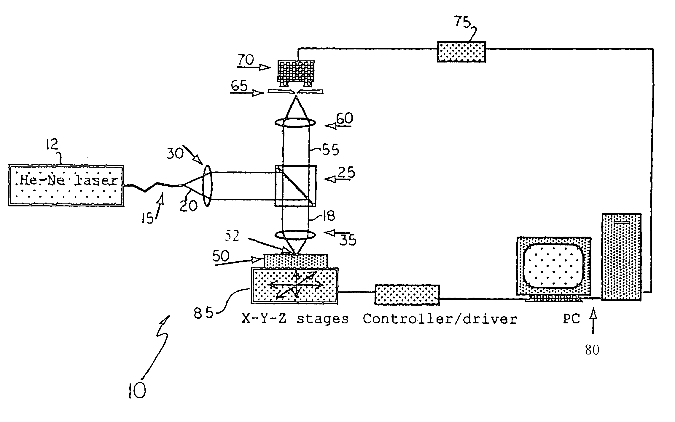
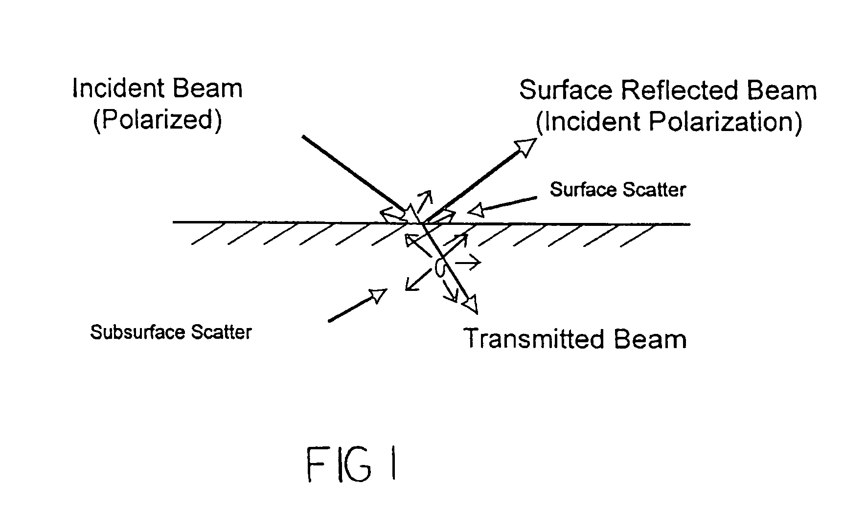
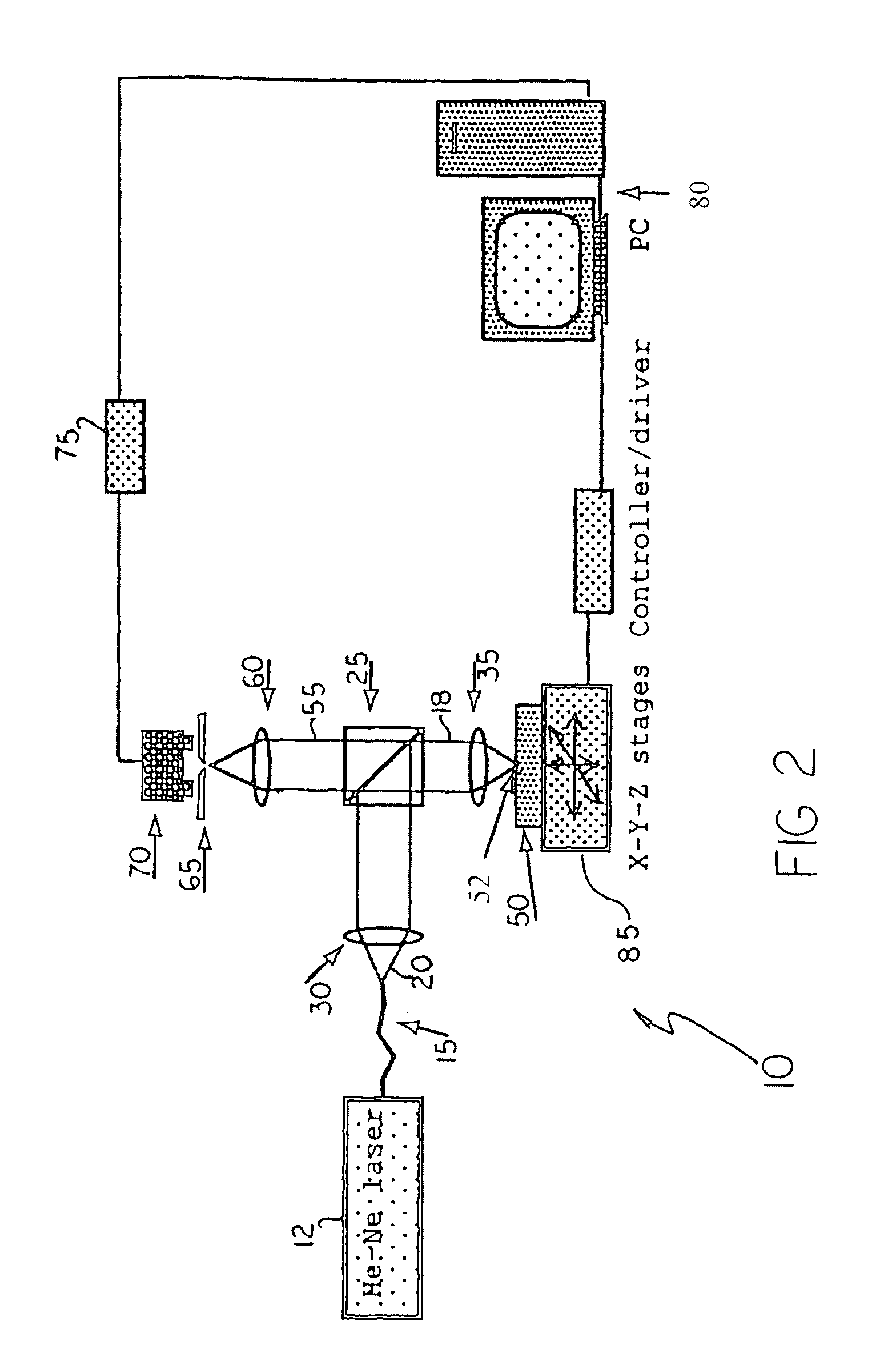
[0030]The present invention comprises a new method and device for depth-resolved detection of subsurface micro-structure and other features in dense materials. The materials the micro-structure of which can be studied with the present method and device include translucent materials such as ceramics, ceramic composites, ceramic coatings, silicon, semiconductors, and biological materials. Examples of subsurface structure that can be detected include air pockets, fault lines, the presence of different grain sizes, changes in porosity, interfaces between different structures / materials, etc. . . . These structures exhibit enhanced back scattering of the incident light.

[0031]The invention utilizes cross-polarization detection of subsurface back-scattering with a scanning confocal system to achieve depth resolution of translucent materials. The depth that can be reached depends on the sensitivity of the detector. With a semi-conductor detector one may detect the back-scatter from a depth t...


PUM


Abstract

A method and a device to detect subsurface three-dimensional micro-structure in a sample by illuminating the sample with light of a given polarization and detecting light emanating from the sample that has a different direction of polarization by means of a confocal optical system.

Description

BACKGROUND OF THE INVENTION[0001]1. Field of the Invention[0002]The present invention relates to the field of confocal microscopy and, more particularly, the present invention relates to high three-dimensional resolution cross-polarization devices for imaging subsurface micro-structure.[0003]2. Description of the Prior Art[0004]Measurement of detailed subsurface micro-structure is critical in determining properties of materials and understanding material processing mechanisms. At present, subsurface micro-structure is typically examined by destructive methods such as: (a) cutting the sample to examine cross-sectional micro-structure; (b) polishing or removing surface layers to examine micro-structure at layers of different depths; (c) cutting or polishing the sample at an angle to the surface. Destructive examination has several disadvantages, including being time consuming, error prone, and inapplicable for live tissues.[0005]Non-destructive methods (such as microscopy) for examini...

Claims


Application Information

Patent Timeline
IPC IPC(8): G01C3/08
CPCG02B21/0024G01N21/21
Inventor SUN, JIANGANG
Owner THE UNITED STATES AS REPRESENTED BY THE DEPARTMENT OF ENERGY
Why Eureka
Try Eureka