Thermal actuator

a technology of actuators and actuators, applied in the field of microelectromechanical systems, can solve the problems of reducing the amount of deflection, altering the thermal gradient of the air surrounding the device, and the separation of the two arms, so as to improve the efficiency of the actuator, maintain the stiffness, and reduce the heat transfer through the air

Active Publication Date: 2006-05-16
LUMENTUM TECH UK LTD +1
View PDF8 Cites 8 Cited by
  • Summary
  • Abstract
  • Description
  • Claims
  • Application Information

AI Technical Summary

Benefits of technology

[0007]In order to improve the efficiency of the actuator in terms of microns of motion of the actuator per Watt, in accordance with the invention the cold arm is spaced further away from the hot arm to reduce the heat transfer through the air while maintaining its stiffness. The size of the flexure element and the hot arm spacing to flexure ...

Problems solved by technology

However, the problem with removing the substrate heat sink is that the thermal gradients set up within the...

Method used


Image

  • Thermal actuator
  • Thermal actuator
  • Thermal actuator

Examples


Embodiment Construction

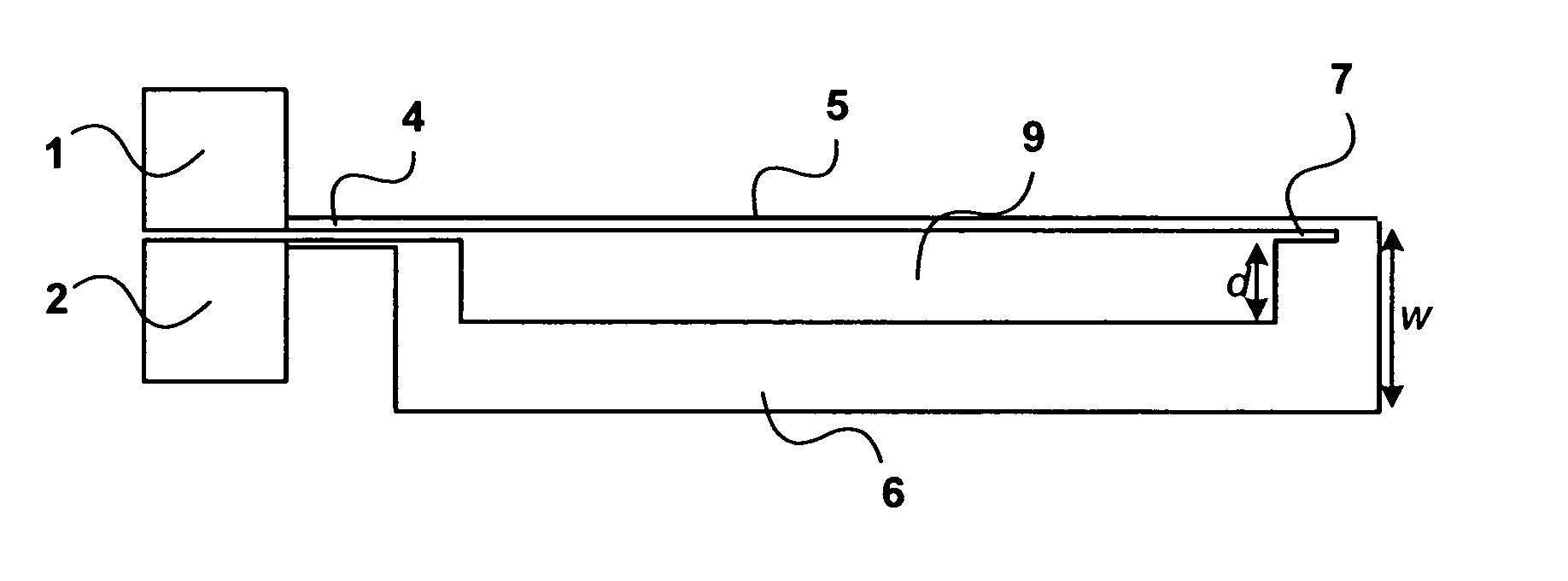
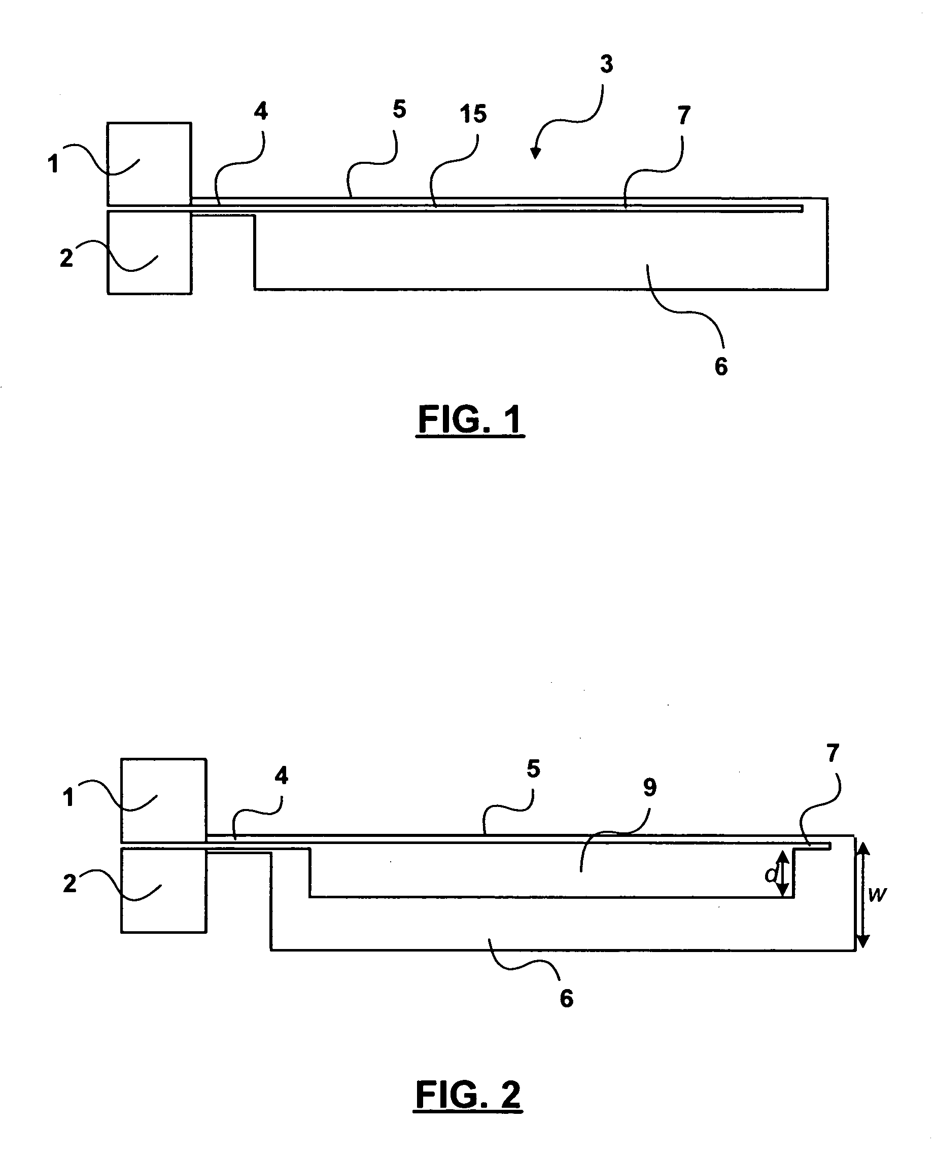
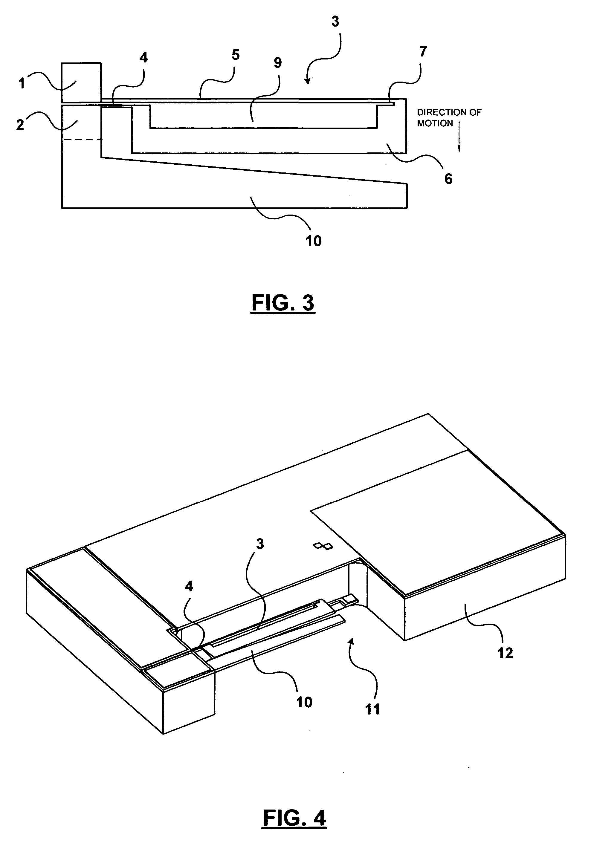
[0018]The standard asymmetric style thermal actuator commonly used in the MEMS community and schematically shown in FIG. 1 comprises a pair of stationary bond pads 1, 2 and an actuator element 3 connected to the bond pads by a narrow flexure portion 4.

[0019]The actuator element 3, which is formed from a common layer of silicon on an insulator substrate, comprises a long narrow hot arm 5 extending alongside and spaced from a wider cold arm 6 by a small gap 7. The actuator element 3 is formed from a single layer of silicon using MEMS technology.

[0020]The actuator element 3 is in the form of a wire formed in a generally U-shape configuration. A current driven through the actuator element between the bond pads 1, 2, from which the arms 5, 6 extend, causes one side of the device to heat and expand more than the other due to the different resistance of the two arms. This difference in thermal expansion sets up an internal mechanical moment and causes the actuator element 3 to deflect towa...


PUM


Abstract

An asymmetric MEMS thermal actuator device includes a base portion, typically a pair of bond pads, and an actuator element connected to the base portion by a flexure portion. The actuator element has a first arm and a second arm alongside the first arm and spaced from the first arm. The second arm is wider than the first arm so that the actuator element deflects about the flexure element due to differential heating in the first and second arms when an electrical current is passed therethrough. A cut-out portion is provided in the second arm adjacent the first arm so as to increase the spacing therefrom over at least a portion of the second arm. Preferably, a heat sink is also provided laterally adjacent the second arm.

Description

CROSS REFERENCE TO RELATED APPLICATION[0001]This application claims the benefit under 35 USC 119(e) of U.S. provisional application Ser. No. 60 / 320,098 filed Apr. 8, 2003.FIELD OF THE INVENTION[0002]This invention relates to micro-electromechanical systems (MEMS) devices, and in particular to an asymmetric thermal actuator suitable for use as a variable optical attenuator in fiber optic systems.BACKGROUND OF THE INVENTION[0003]Variable Optical Attenuators (VOAs) are used in fiber optic systems to control the amount of light falling, for example, on a detector. For this purpose, it is known to use an asymmetric style MEMS electro thermal actuator. This can be fabricated using bulk silicon-on-insulator wafers. A known asymmetric actuator consists of a cantilevered electrical loop having a narrow hot arm, a wide cold arm and a narrow flexure element. When current is passed through the loop, the narrow arm heats up more than the wide cold arm, and as a result causes the actuator to flex...

Claims


Application Information

Patent Timeline
IPC IPC(8): F01B29/10B81B3/00G02B26/08G11B5/56G11B21/24
CPCB81B3/0024B81B3/004G02B26/0866B81B2201/047H01H2061/008B81B2203/033B81B2203/058B81B2203/0118
Inventor HICKEY, RYAN MURRAY
Owner LUMENTUM TECH UK LTD
Why Eureka
Try Eureka