
Shock absorber

a technology of shock absorber and shock absorber, which is applied in the direction of shock absorbers, borehole/well accessories, surveys, etc., can solve the problems of affecting affecting the transmission of shock wave energy along the tool string, etc., and achieves the effect of increasing the dampening effect and increasing the effectiveness of the piston

Inactive Publication Date: 2006-05-16
SONDEX
View PDF15 Cites 44 Cited by
  • Summary
  • Abstract
  • Description
  • Claims
  • Application Information

AI Technical Summary

Benefits of technology

[0016]Preferably, the mass or body comprises a piston suspended on the two springs to provide a further dampening effect. The effectiveness of the piston may be increased by using deformable plugs inside the piston to absorb energy as the piston is compressed or as it is stretched.
[0017]Preferably, one of the terminal housings is also provided with a strong cable or wire rope which limits the maximum extension of the springs such that they are not extended beyond their yield point or elastic limit. This is advantageous when the shock absorbing tool, or the tool string on which it is mounted becomes stuck or jammed in the bore hole and a larger than normal force is required to free the tool or tool string. This force is borne by the cable or wire rope and not the springs where it might cause damage.

Problems solved by technology

Thus, much of the energy from the shock wave is delayed from transmission along the tool string.

Method used


Image

  • Shock absorber
  • Shock absorber
  • Shock absorber

Examples


Embodiment Construction

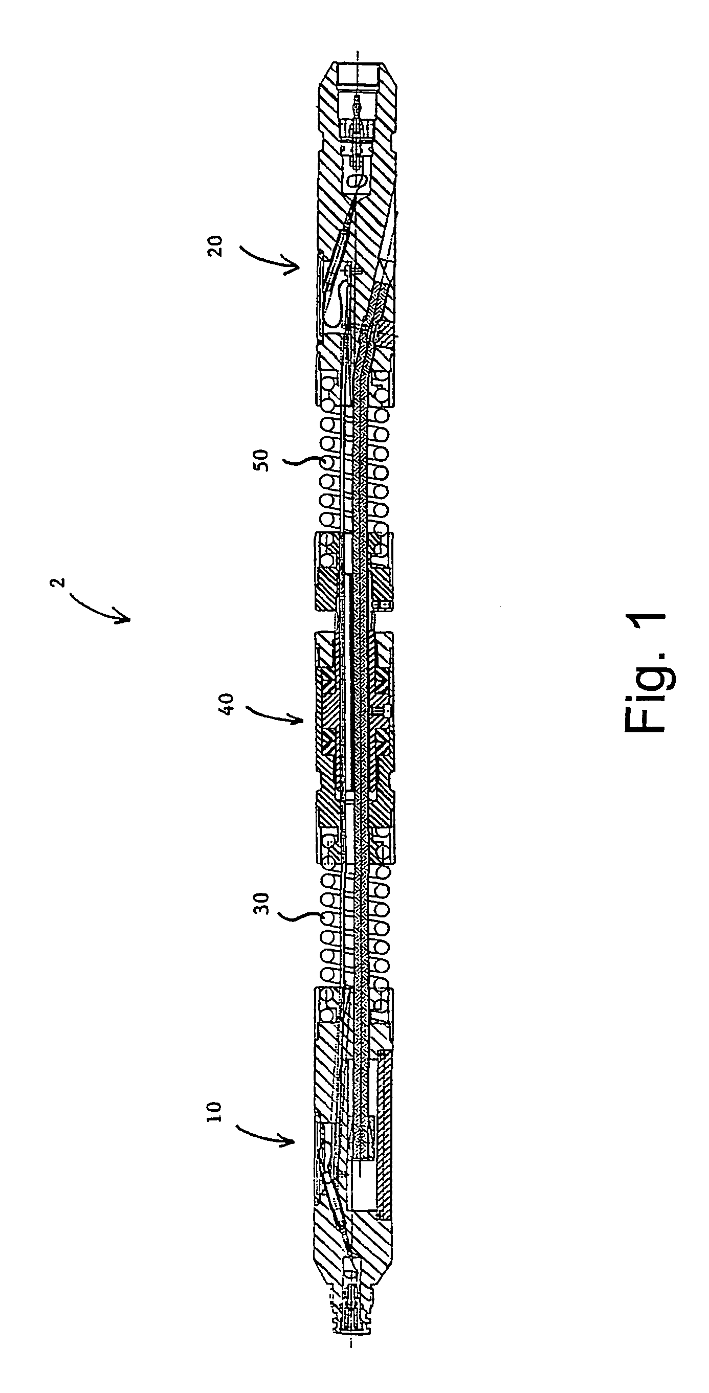
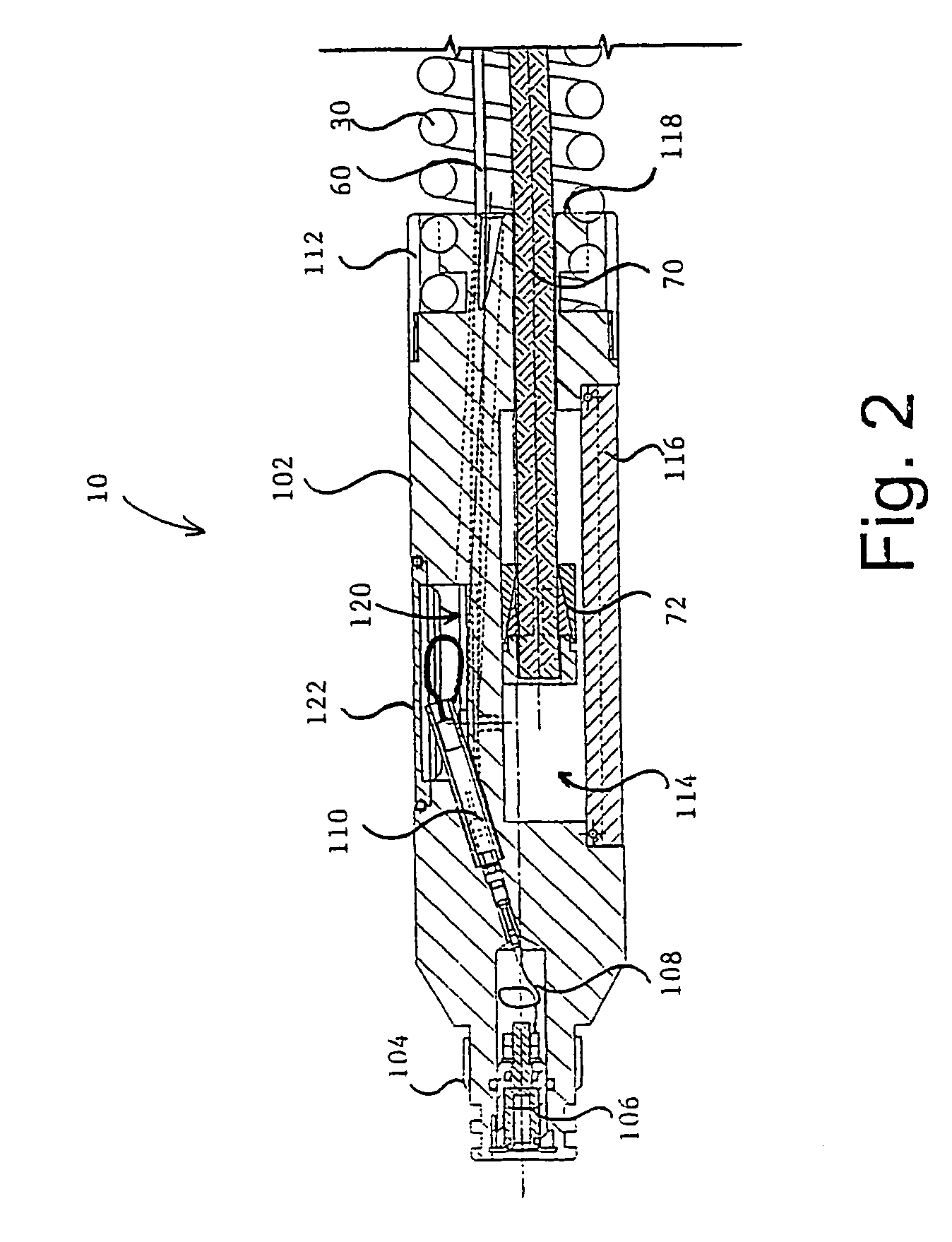
[0023]A shock absorbing tool 2 according to the preferred embodiment of the invention will now be described with reference to FIG. 1. The tool is intended for use as part of a tool string in a bore hole or pipeline and is therefore elongate in shape and is provided with a male end terminal housing 10 and a female end terminal housing 20 so that it may be mechanically and electrically connected to other neighbouring tools in the tool string. The male and female terminal housings 10 and 20 are cylindrical in shape, have a diameter which is narrow in comparison to their length and are disposed apart from each other on the same longitudinal axis, being orientated so that the parts of the terminal housing which connect to adjacent tools in the tool string face away from each other.

[0024]In the preferred embodiment shown in FIG. 1, the diameter of the terminal housings is approximately 50 mm; the length is approximately 250 mm.

[0025]Connected at one end to the inside end of male terminal ...


PUM


Abstract

A shock absorbing tool for use in pipelines and oil wells, particularly in combination with perforation guns comprises a central mass supported on two springs between the end terminal members. The shock wave is absorbed in the free oscillation of the mass. The mass is constituted by a piston assembly. A steel rope permits the shock absorbing tool to be maneuvered within the bore hole without damage to the springs.

Description

BACKGROUND OF THE INVENTION[0001]This application relates to a shock absorber apparatus for use as part of a tool string for use in bore holes and / or pipelines. This invention particularly though not exclusively relates to a shock absorbing tool for use with perforating guns in the oil well logging industry.[0002]Present day wells for extracting oil, gas or water, are mostly constructed by drilling in the ground and placing a tubular steel casing as a liner in the well. Once the casing is in place, the well may be completed using a perforating gun to form perforations in the casings through which surrounding reservoir fluid, comprising oil, gas and water, may flow inwardly. From this reservoir fluid, the oil, gas or water may then be extracted.[0003]A perforating gun is an instrument equipped with a number of powerful explosives or ‘shape charges’. These are about one inch (25 mm) in diameter, and when detonated produce a plasma which destroys both the steel pipeline casing and typi...

Claims


Application Information

Patent Timeline
IPC IPC(8): E21B17/07F16F7/116E21B47/01
CPCE21B47/011E21B17/07E21B47/017
Inventor MASON, GUY HARVEYSTUART-BRUGES, WILLIAM PETERSEARIGHT, THOMAS LEMPRIEREHITCHCOCK, IAN
Owner SONDEX
Learn More