Forming method for milling threads of variable tooth worms

a technology of variable tooth worms and forming methods, which is applied in the direction of worms, gear teeth, gearing elements, etc., can solve the problems that the simons method for forming involute worms cannot be used, and achieve the effects of less machining hours, more powerful cutting force, and high productivity

Inactive Publication Date: 2006-05-16
TSUBAKI EMERSON GEAR TIANJIN
View PDF11 Cites 5 Cited by
  • Summary
  • Abstract
  • Description
  • Claims
  • Application Information

AI Technical Summary

Benefits of technology

[0007]The advantages and the effect of this invention show that the machining method of this invention has higher productivity, more powerful cutting force, less machining hours and reaches higher machining accuracy as

Problems solved by technology

Therefore, Simmons method for forming the involute worms can not be used for forming the threa

Method used


Image

  • Forming method for milling threads of variable tooth worms
  • Forming method for milling threads of variable tooth worms
  • Forming method for milling threads of variable tooth worms

Examples


embodiment 1

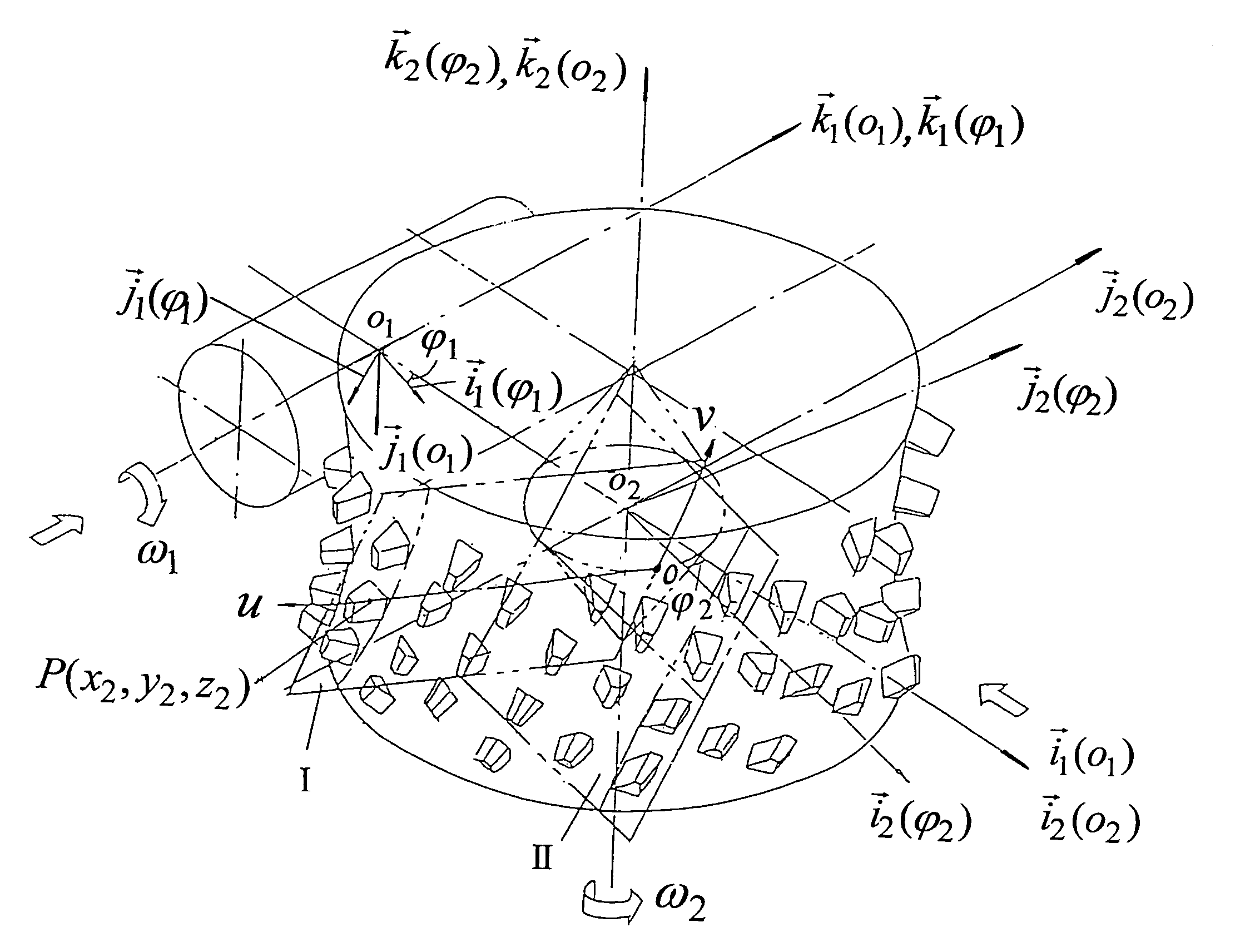
[0019]On a five-simultaneously-working-axis CNC machine-tool, given that a VTW worm to be machined has β=18° the inclination angle of the generatrix plane, d1=50.2 mm the reference diameter, and the center distance between the worm blank and the milling-cutter a=101.6 mm, the milling-cutter performs a cutting movement relatively to the worm blank with the transmission ratio between the worm blank and the milling cutter i=41 / 4; the worm blank rotates around {right arrow over (k)}1(φ1)-axis at angular speed {right arrow over (ω)}1, while the milling cutter rotates about {right arrow over (k)}2(φ2)-axis at angular speed {right arrow over (ω)}2 and simultaneously makes a radial feed along {right arrow over (i)}2(o2)-axis and a peripheral feed around {right arrow over (k)}2(φ2)-axis. The radius of the main basic circle of the milling cutter rb=33 mm and the coordinate values of the cutting edge of the milling cutter are described according to the following equations

x2=u,

y2=rb−v sin β,

z2=...

embodiment 2

[0027]On a five-simultaneously-working-axis CNC machine-tool, given that a VTW worm to be machined has β=18° the inclination angle of the generatrix plane, d1=50.2 mm the reference diameter, and the center distance between the worm blank and the milling-cutter a=101.6 mm, the milling-cutter performs a cutting movement relatively to the worm blank with the transmission ratio between the worm blank and the milling cutter i=41 / 4.

[0028]Besides rotating around {right arrow over (k)}1(φ1)-axis at angular speed {right arrow over (ω)}1, the worm blank also makes a slight axial displacement along {right arrow over (k)}1(φ1)-axis with the value Δk1=1.05 mm in order to make the reference toroid of VTW worm become an elliptic or parabolic one.

[0029]While the milling cutter rotates about {right arrow over (k)}2(φ2)-axis at angular speed {right arrow over (ω)}2 and simultaneously makes a radial feed along {right arrow over (i)}2(o2)-axis and a peripheral feed around {right arrow over (k)}2(φ2)-ax...


PUM

PropertyMeasurementUnit
Lengthaaaaaaaaaa
Lengthaaaaaaaaaa
Lengthaaaaaaaaaa

Abstract

A forming method for milling teeth of variable tooth worms (VTW) with the following features: on a multi-axis simultaneously-working CNC machine-tool a moving coordinate system {σ11)[O1;{right arrow over (i)}11),{right arrow over (j)}11),{right arrow over (k)}1 1)]} is correlated to the worm blank of the VTW worms, whereon the worm blank of the VTW worms rotates around {right arrow over (k)}11)-axis at angular speed |{right arrow over (ω)}1|; another moving coordinate system {σ22)[O2; {right arrow over (i)}22), {right arrow over (j)}22), {right arrow over (k)}22)]} is correlated to the milling cutter, whereon the milling-cutter rotates around {right arrow over (k)}22)-axis at angular speed |{right arrow over (ω)}2|, |{right arrow over (ω)}1|/|{right arrow over (ω)}2|=i12 and i12 is a constant; the feed motion of the milling cutter comprises the radial shift along {right arrow over (i)}2(o2)-axis and the peripheral shift around {right arrow over (k)}22)-axis; the equations of the cutting edge of the milling cutter are given as below
x=u
y2=rb−v sin β
z2=v cos β.

Description

CROSS REFERENCE TO RELATED APPLICATION[0001]This application is a continuation-in-part application of application Ser. No. 09 / 978,340 now abandoned, filed Oct. 17, 2001, entitled “METHOD OF FORMING MILLED TOOTH OF VARIABLE TOOTH WORM”.FIELD OF THE INVENTION[0002]This invention relates to a forming method for milling the threads of cylindrical variable tooth worms.BACKGROUND OF THE INVENTION[0003]The worm transmissions may be classified into two sorts: the first sort is a cylindrical worm transmission; the second one is a toroidal worm transmission. While the cylindrical worms can further be classified into an involute helicoid worm (ZI for short, the same hereinafter), an Archimedes worm (ZA), a milled helicoid worm (ZK), and a variable tooth worm (VTW) disclosed in China patent No. ZL96244108.2 and U.S. Pat. No. 6,176,148B1 with accordance to the different profile thereof. The worms of ZI-, ZA- and ZK-type can all be formed by lathing with different-profile cutters. However, the re...

Claims


Application Information

Patent Timeline
IPC IPC(8): B23F11/00B23F13/00B23F13/02
CPCB23F13/02Y10T409/107473Y10T409/103021Y10T409/101749
Inventor ZHANG, YAXIONGQI, LIN
Owner TSUBAKI EMERSON GEAR TIANJIN
Why Eureka
Try Eureka