Magnetic recording disk and process for manufacture thereof

a recording disk and magnetic technology, applied in the field of magnetic recording disks, can solve the problems of hydrofluoric acid being liable to corrode the element portion of the magnetic head, troublesome flying stiction, etc., and achieve excellent lubrication, heat resistance and coating performance, and increase the information recording capacity.

Active Publication Date: 2006-05-16
WESTERN DIGITAL TECH INC
View PDF3 Cites 70 Cited by
  • Summary
  • Abstract
  • Description
  • Claims
  • Application Information

AI Technical Summary

Benefits of technology

[0047]According to the present invention, there can be obtained a magnetic recording disk having excellent lubrication, adhesion, heat-resistance and coating performances, so that the troubles of fly-stiction, corrosion, head clash, migration and the like can be prevented, and the magnetic recording disk of the present invention is suitable for increasing the information recording capacity.PREFERRED EMBODIMENTS OF THE INVENTION
[0048]The magnetic recording disk of the present invention has a constitution in which at least a magnetic layer, a protective layer and a lubricant layer are consecutively formed on a substrate, and a combination of the following compounds (A) and (B) are incorporated into the above lubricant layer.
[0049]The compound (A) is a compound that has the structure of the general formula (I),
[0050]wherein each of p and q is an integer of 1 or more, and in which diethanolaminomethyl groups are bonded to carbon atoms of the two end moieties of a perfluoropolyether main chain, one diethanolaminomethyl group bonded to the carbon atom of one end moiety, one diethanolaminomethyl group bonded to the carbon atom of the other end moiety.
[0051]The above compound (A) suitably has lubrication performance based on its main chain and has high heat resistance and high capability of adhesion to a protective layer based on two —CH2CH2OH functional groups of each of the two end moieties of the main chain. However, the functional groups have high capability of adhesion to the protective layer, and as a result, the lubrication performance is reduced. There is therefore a problem that the compound (A) is liable to cause a clash trouble, and it is difficult to use the compound (A) alone, which is the problem that the present inventors have sought to overcome.
[0052]On the other hand, the compound (B) has a structure in which its perfluoropolyether main chain has two end moieties each of which contains a carbon atom or a hydrogen atom to which a hydroxyl-containing hydrocarbon group that optionally contains an ether bond is bonded. The compound (B) suitably has flexible lubrication performance based on the perfluoropolyether main chain and capability of adhesion to the protective layer based on two terminal functional groups having hydroxyl groups. However, the compound (B) has a problem in low heat resistance. Further, the compound (B) is liable to cause a migration trouble and has a difficulty in suitable control in use. It is therefore difficult to use the compound (B) alone. These are problems that the present inventors have sought to overcome.

Problems solved by technology

As a result, lubricant having an increased flowability is transferred to, and deposited on, a magnetic head positioned within an extremely small distance from the magnetic recording disk, so that the flying position of the magnetic head is destabilized, which causes a fly stiction trouble.
It has been also found that the lubricant, when thermally decomposed, forms hydrofluoric acid in some cases, and that the hydrofluoric acid is liable to corrode the element portion of a magnetic head as a result of transfer and deposition thereof to / on the magnetic head.

Method used


Image

  • Magnetic recording disk and process for manufacture thereof
  • Magnetic recording disk and process for manufacture thereof
  • Magnetic recording disk and process for manufacture thereof

Examples


example 1

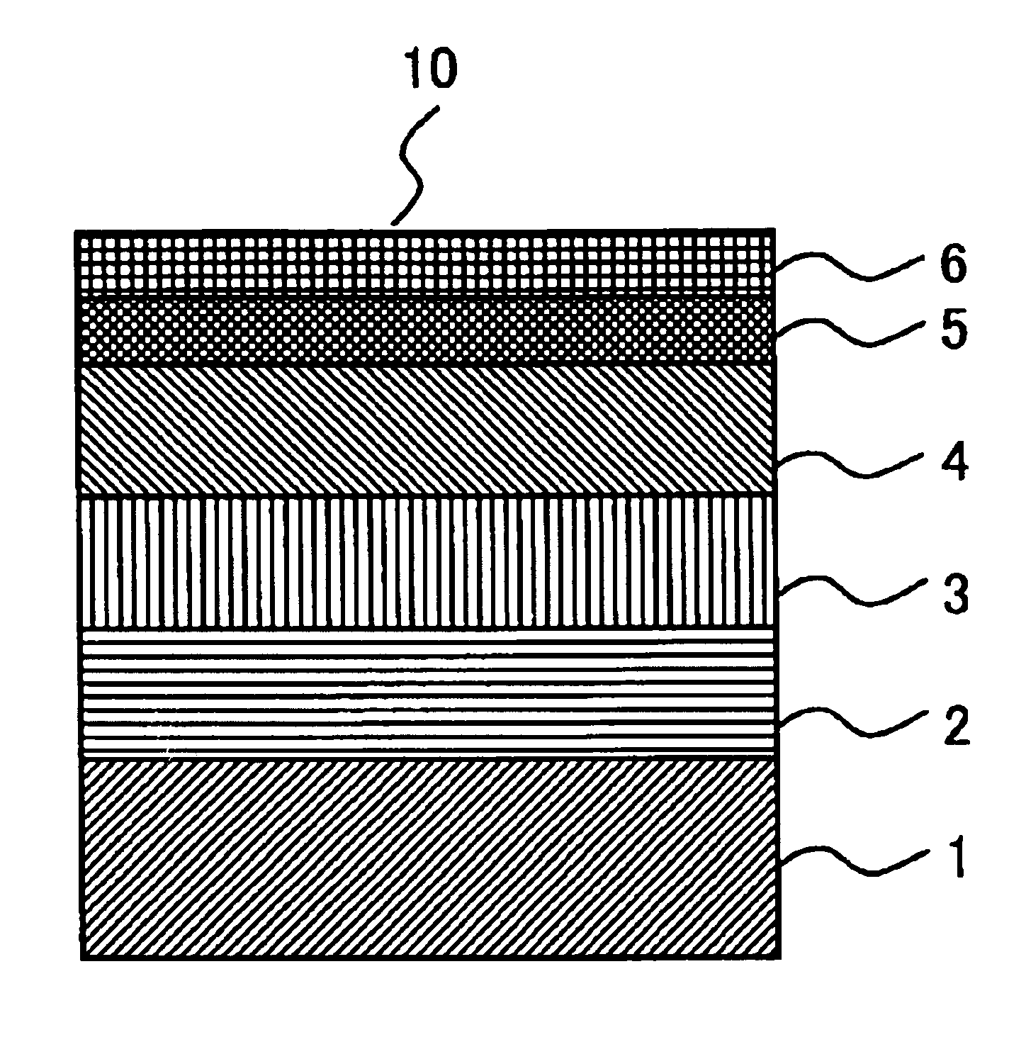
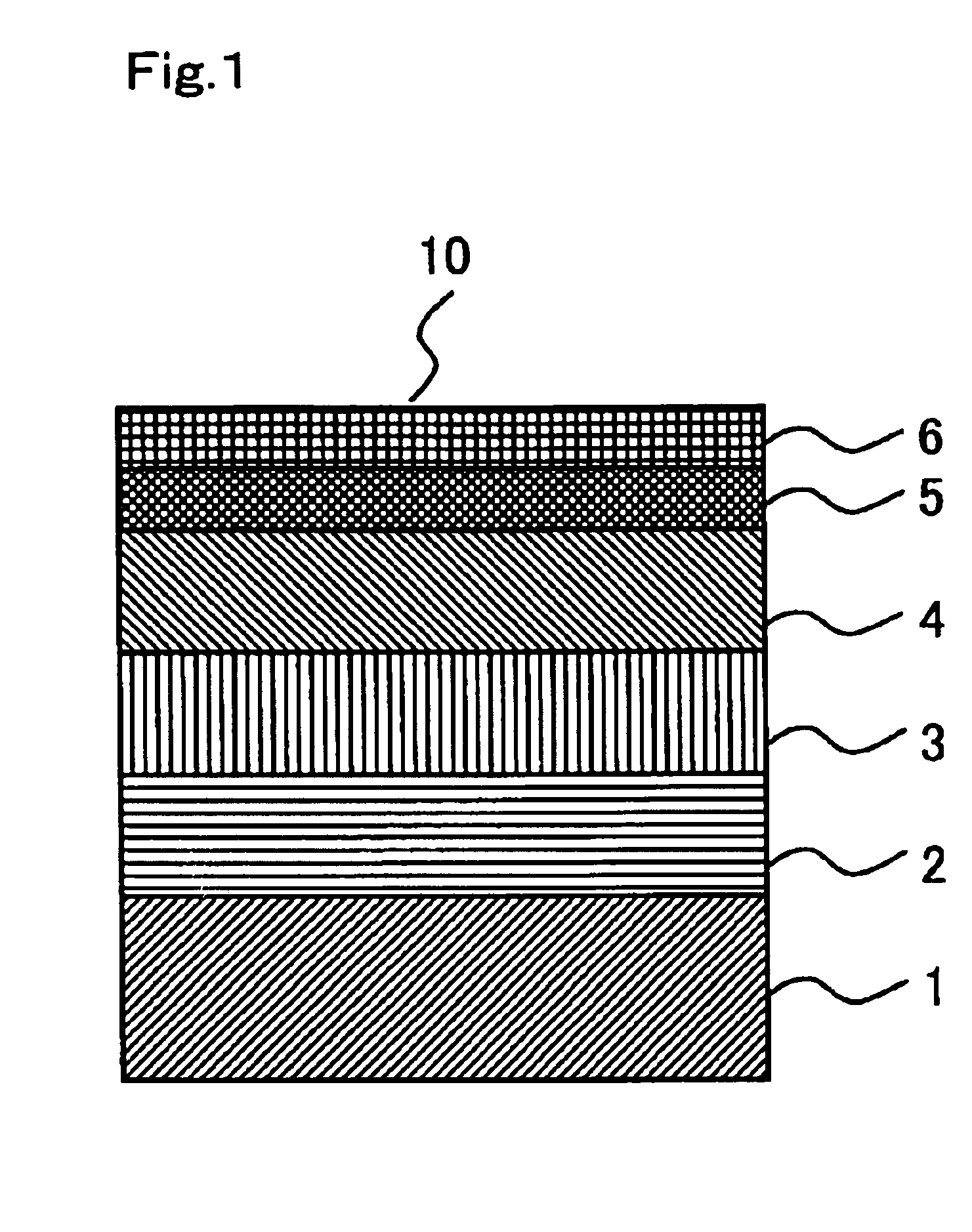
[0092]FIG. 1 is cross-sectional view of a magnetic recording disk 10 for schematically showing the layer structure of one embodiment of the magnetic recording disk of the present first invention. In the magnetic recording disk 10, a seed layer 2, an undercoat layer 3, a magnetic layer 4, a protective layer 5 and a lubricant layer 6 are consecutively formed on a substrate 1.

[0093]The substrate 1 is a chemically strengthened aluminosilicate glass substrate, and the main surface thereof is mirror-polished and hence has an Rmax of 4.8 nm and an Ra of 0.43 nm. Further, the glass substrate 1 has a diameter of 65 mm and a thickness of 0.635 mm and is used for a 2.5-inch magnetic recording disk.

[0094]The seed layer 2 is formed of an NiAl alloy containing 50 mol % of Ni and 50 mol % of Al and has a thickness of 30 nm.

[0095]The undercoat layer 3 is formed of a CrMo alloy containing 80 mol % of Cr and 20 mol % of Mo and has a thickness of 8 nm .

[0096]The magnetic layer 4 is formed of a CoPt al...


PUM

PropertyMeasurementUnit
flying heightaaaaaaaaaa
molecular weight distributionaaaaaaaaaa
polydispersityaaaaaaaaaa

Abstract

A magnetic recording disk has a high-adhesion lubricant layer that permits an operation at an extremely low level of flying height of 12 nm or less without troubles and which is capable of preventing the migration at a high-speed rotation, and comprises a substrate, a magnetic layer formed on the substrate, a protective layer formed on the magnetic layer and a lubricant layer formed on the protective layer, the lubricant layer containing a compound (A) of the general formula (I), wherein each of p and q is an integer of 1 or more, anda compound (B) having a perfluoropolyether main chain having two end moieties each of which contains a carbon atom or an oxygen atom to which a hydroxyl-containing hydrocarbon group that optionally contains ether bond(s) is bonded, and a process for the manufacture thereof is provided.

Description

TECHNICAL BACKGROUND[0001]1. Field of the Invention[0002]The present invention relates to a magnetic recording disk and a process for the manufacture thereof. More specifically, the present invention relates to a magnetic recording disk which has a high-adhesion lubricant layer so that a fly stiction trouble or a corrosion trouble can be prevented even at an extremely low level of flying height, for example, of 12 nm or less and that migration can be prevented even at a high-speed rotation, for example, of 5,400 rpm or more and which is to be mounted on a magnetic recording disk unit such as a hard disk drive unit (HDD), and a process for manufacture thereof.[0003]2. Statement of Related Art[0004]Conventionally, a magnetic recording disk unit employs a CSS (Contact Start and Stop) method in which a magnetic head is kept in contact with a contact start and stop region (CSS region) formed in an inner-circumferential region at a stop time, the magnetic head is allowed to come up slight...

Claims


Application Information

Patent Timeline
Patent Type & Authority Patents(United States)
IPC IPC(8): G11B5/71C10M105/54B32B27/28C10M105/62C10M107/38C10M107/44C10N20/04C10N40/18G11B5/64G11B5/72G11B5/725G11B5/84
CPCB32B27/28G11B5/725G11B5/8408Y10T428/3154G11B5/7257
Inventor SHIMOKAWA, KOICHI
Owner WESTERN DIGITAL TECH INC
Why Eureka
Try Eureka