Laminated structure and method of forming same

a technology of laminate structure and forming method, which is applied in the field of laminate structure, can solve the problems of undesirable curling edges, and achieve the effect of reducing curling and alleviating curling

Inactive Publication Date: 2006-05-16
CHAOZHOU THREE CIRCLE GRP
View PDF12 Cites 14 Cited by
  • Summary
  • Abstract
  • Description
  • Claims
  • Application Information

AI Technical Summary

Benefits of technology

[0014]The edge strip of green sinterable material applied to the edge or edges of the first layer may be continuous or formed in plural parts. The edge strip may be formed and applied to the first layer in a variety of different ways. In one embodiment, the edge strip is tape cast, bonded and pressed onto the first layer. In another embodiment, the edge strip may be screen printed onto the first layer. The edge strip may stand wholly proud of the first layer, or may be partially or wholly embedded in the first layer. Without wishing to be bound by theory, it is believed that the edge strip alleviates curling of the at least one edge by restricting the movement of the particles of the first layer during sintering.
[0015]Partly or wholly embedding the edge strip in the first layer will density the at least one edge of the first layer. This can be advantageous where the sintered laminated structure is used to form a fuel cell since a glass or other seal material which softens at the elevated operating temperature of a fuel cell can be applied to the at least one edge of the first layer and be absorbed into the denser edge region with less risk of the softened seal material spreading to the less dense portion of the first layer remote from the at least one edge. Thus, the seal material may be absorbed into the edge region of the first layer but be prevented from spreading into a core region by capillary action.
[0019]Like its shrinkage rate, sinterability and porosity, the thickness of the edge strip may be chosen by trial and error so as to minimise curling at the edge portion of the laminated structure, while alleviating other undesirable effects such as cracking, delaminating and deformation of the second layer opposite the edge strip. The thickness of the edge strip is preferably within about 25% of that of the second layer, partly dependent upon the relative densities of the materials.
[0020]The green sinterable materials of the first layer, second layer and edge strip will contain binder material in order to hold the particulate ceramic or ceramic-like material together prior to firing. The densities and shrinkage rates of the respective layers and edge strip may be controlled to a degree by adjusting the binder content, but the freedom to manipulate the binder content of the first and second layers will be restricted in the usual way by the requirements of the green material and of the sintered material. However, the binder content of the edge strip may be conveniently adjusted by trial and error to provide the optimum shrinkage therein with no curling of the at least one edge. With similar sinterable materials for the edge strip and the second layer it is believed that the optimum binder content in the edge strip is slightly less than that of the second layer, for example in the range 10 to 20% less, preferably about 15% less. This has been found to avoid the edge strip creating a step at the edge portion of the laminated structure, while providing the desired alleviation of curling. Suitable binder materials for the edge strip and other layers include polyvinyl butyral. The second layer may have a binder content in the range of, for example, 20 to 25 wt % of the sinterable material.

Problems solved by technology

This is a particular problem where the curled edges are not desirable, for example when the edges of the laminated structure are intended to have seals applied to them, such as when the laminated structure forms part of a planar solid oxide fuel cell.

Method used


Image

  • Laminated structure and method of forming same
  • Laminated structure and method of forming same

Examples


Embodiment Construction

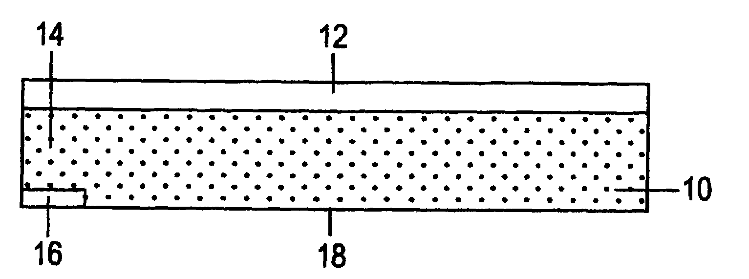
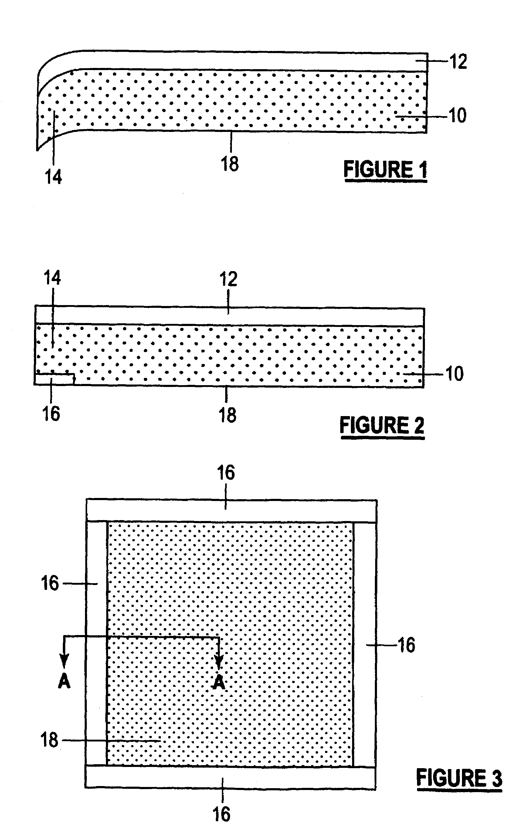
[0028]Referring to FIG. 1, there is shown part of a sub-structure of a solid oxide fuel cell comprising an anode layer 10 and an electrolyte layer 12, including one edge portion 14 of the sub-structure. The overall sub-structure has a rectangular configuration with dimensions of about 110×90 mm, and the anode layer 10 has a thickness in the range of about 0.5 to 1.0 mm, for example 0.9 mm, while the solid oxide electrolyte layer 12 has a thickness in the range of 10 to 50 microns, for example about 20 microns. These dimensions are given by way of illustration only, and other arrangements are possible. For example, as described the anode layer 10 will be the support structure in the fuel cell, but in other embodiments a thicker electrolyte layer may be used as the support layer for a thinner anode layer.

[0029]The solid oxide electrolyte layer 12 comprises Y2O3-doped ZrO2 (YSZ) which has been sintered into a dense layer to provide a barrier to fuel gas on the side of the anode layer 1...


PUM

PropertyMeasurementUnit
shrinkage rateaaaaaaaaaa
porosityaaaaaaaaaa

Abstract

A method of alleviating edge curling when laminated structures comprising layers of green material having different shrinkage rates are sintered comprises applying to a face (18) of edges (14) the first layer (10) having the higher shrinkage rate green sinterable material, opposite to the second layer (12) having the lower shrinkage rate green sinterable material, an edge strip (16) of a green sinterable material also having a shrinkage rate lower than the first layer, and then firing the laminated structure. The edge strip may be partly or, advantageously, wholly embedded in the first layer. The sinterable materials of the second layer and edge strip may be the same or similar. The invention is particularly applicable to solid oxide fuel cell sub-structures in which the first layer is the anode layer and the second layer is the electrolyte layer.

Description

BACKGROUND OF THE INVENTION[0001]The present invention relates to laminated structures and is particularly concerned with green and sintered laminated structures and with a method of forming a sintered laminated structure.[0002]When two layers of particulate ceramic or ceramic-like, eg. cermet, materials having different shrinkage rates are laminated and then sintered, there is a tendency for the edges of the laminated structure to curl away from the layer having the lesser shrinkage rate as shrinkage of the layer having the greater shrinkage rate is resisted by the layer having the lesser shrinkage rate. This is a particular problem where the curled edges are not desirable, for example when the edges of the laminated structure are intended to have seals applied to them, such as when the laminated structure forms part of a planar solid oxide fuel cell. The invention is particularly applicable to planar solid oxide fuel cells and, for convenience only, will be described hereinafter g...

Claims


Application Information

Patent Timeline
Patent Type & Authority Patents(United States)
IPC IPC(8): H01M4/86H01M8/12B28B11/00B32B18/00C04B35/01C04B35/486H01M4/88H01M8/02
CPCB32B18/00C04B35/016C04B35/486H01M8/1206B32B37/0015C04B2237/704B32B2307/734B32B2315/02Y02E60/521Y02E60/525C04B2237/348C04B2237/52C04B2237/561C04B2237/565C04B2237/586C04B2237/68C04B2237/702H01M8/1231Y02E60/50
Inventor DONELSON, RICHARDLIN, THERESA
Owner CHAOZHOU THREE CIRCLE GRP
Why Eureka
Try Eureka