
CMOS-based receiver for communications applications

a technology of cmos-based receivers and receivers, applied in the field of cmos-based receivers, can solve the problems of low linearity of cmos-based receivers, low cost and complexity of manufacturing bicmos-based receivers, and low noise of currently available cmos-based receivers

Inactive Publication Date: 2006-05-16
AVAGO TECH INT SALES PTE LTD
View PDF8 Cites 17 Cited by
  • Summary
  • Abstract
  • Description
  • Claims
  • Application Information

AI Technical Summary

Benefits of technology

The solution enhances the sensitivity and linearity of CMOS-based receivers by effectively reducing flicker noise, leading to improved performance and potentially lower manufacturing costs through simplified manufacturing processes.

Problems solved by technology

Unfortunately, BiCMOS technology requires that a high number of masks be used when manufacturing receivers.
Hence, the costs and complexity of manufacturing BiCMOS-based receivers are relatively high.
However, the noise of currently-available CMOS-based receivers is relatively high, and the linearity provided by such receivers still leaves much to be desired.
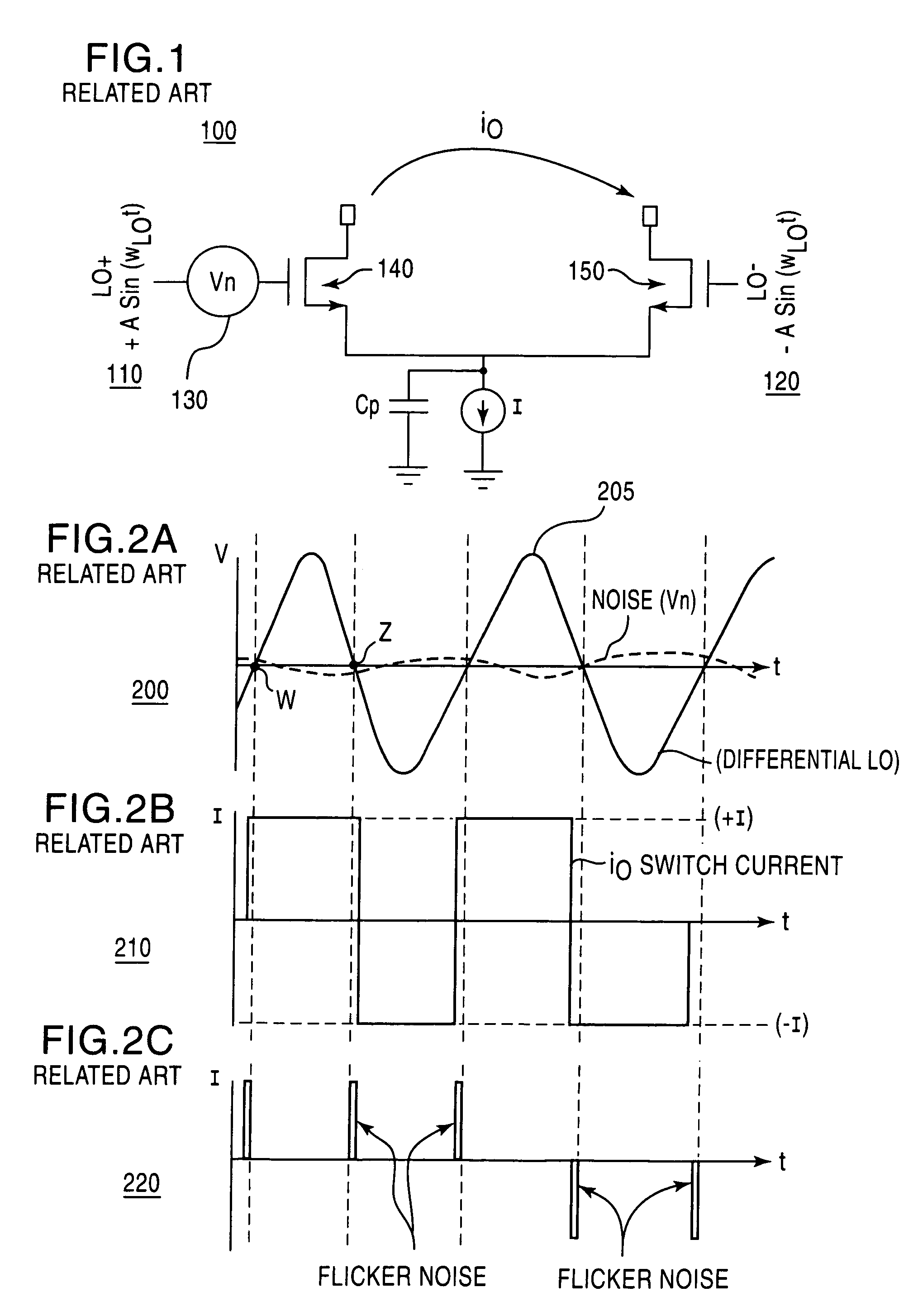
This offset reduces the sensitivity and linearity of currently-available CMOS-based wireless communication devices.

Method used


Image

  • CMOS-based receiver for communications applications
  • CMOS-based receiver for communications applications
  • CMOS-based receiver for communications applications

Examples


Embodiment Construction

)

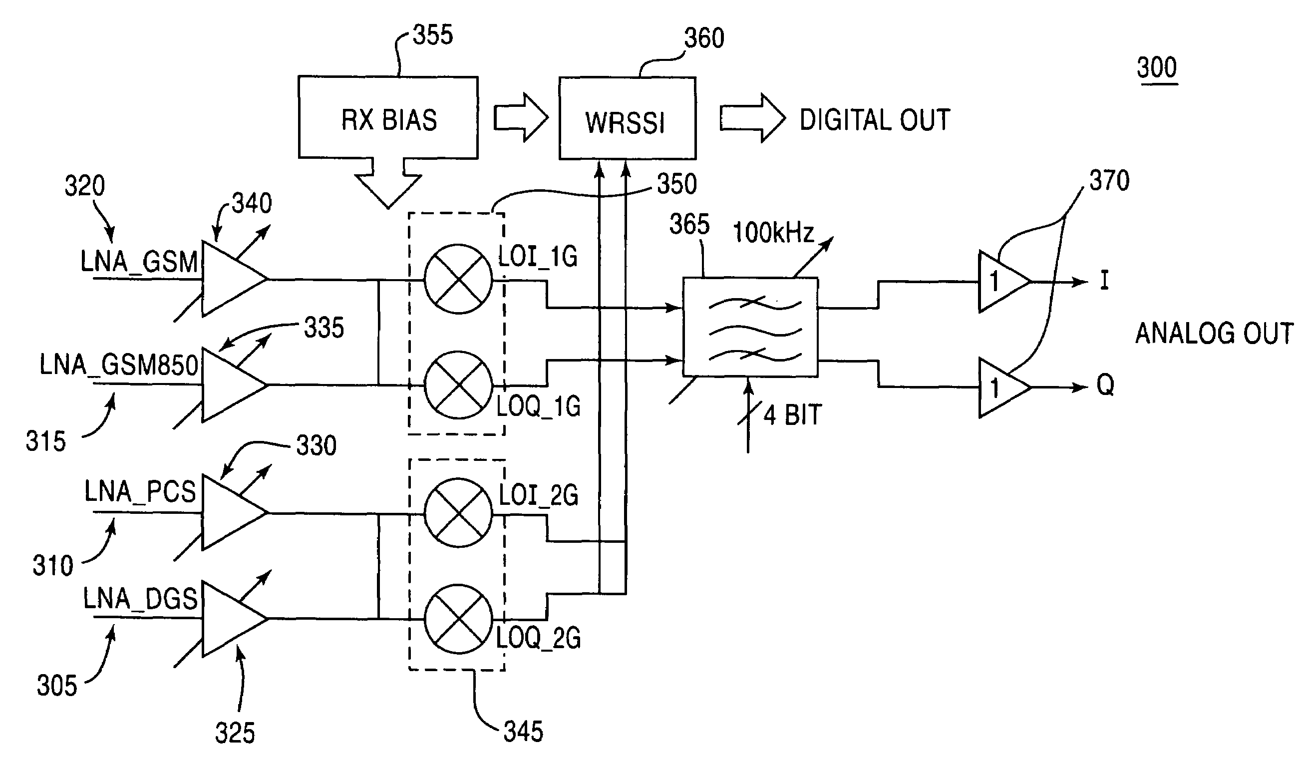
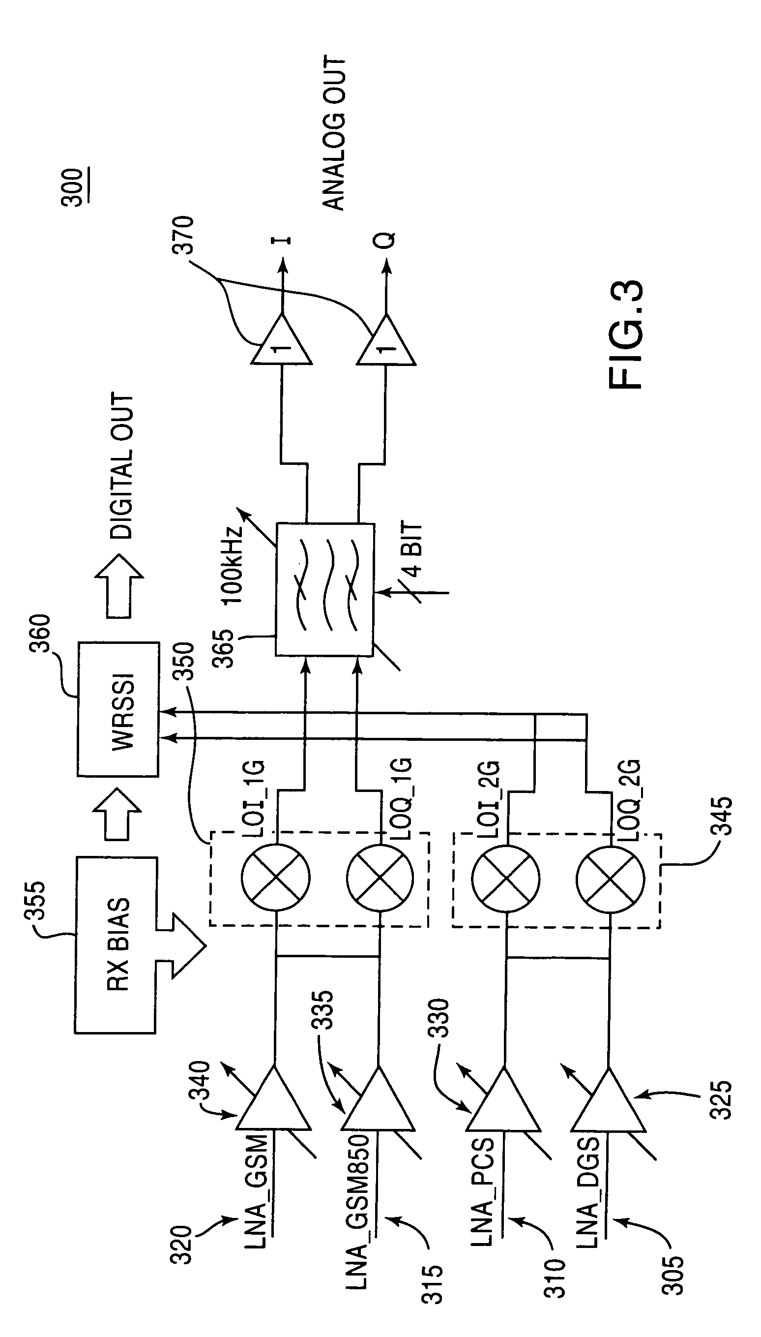
[0026]FIG. 3 illustrates a block diagram of a representative receiver 300 according to certain embodiments of the present invention. It should be noted that any or all of the components included in the block diagram may be differential, including the inputs to the amplifiers discussed below.

[0027]The representative receiver 300 includes a front end region that includes four signal inputs 305, 310, 315, 320, four low-noise amplifiers (LNAs) 325, 330, 335, 340, and two IQ mixers 345, 350. Representative receiver 300 also includes receiver (RX) bias 355, Wide-Band Received Signal Strength Indicator (WRSSI) circuit 360, filter 365, and amplifiers 370. One skilled in the art of the present invention will appreciate that receivers, transceivers, and other devices according to certain embodiments of the present invention may include components other than those illustrated in FIG. 3. Also, one skilled in the are will appreciate that one or more of the components illustrated in FIG. 3 may b...


PUM


Abstract

A receiver and receiver front end having multiple independent differential inputs, multiple independent differential low-noise amplifiers, and two sets of double-balanced IQ mixers. The double-balanced mixers include cross-coupled PMOS devices that dynamically inject current at zero-crossing points to cancel out tail currents in the mixers. Also, methods of operating the above-discussed receiver and receiver front end.

Description

BACKGROUND OF THE INVENTION[0001]1. Field of the Invention[0002]Certain embodiments of the present invention are generally directed at receivers that may, for example, be used for cellular system applications. Certain other embodiments of the present invention are generally directed at methods for operating such receivers.[0003]2. Description of the Related Art[0004]As personal, mobile, wireless communication devices have become more and more prevalent, low-cost, low-power receivers that may be implemented in such devices have been developed. Such receivers are generally preferred to have high degrees of sensitivity and linearity, particularly when used in receiver front-end portions. Therefore, because it has been demonstrated that bipolar complimentary metal oxide semiconductor (BiCMOS) technology is capable of providing the sensitivity and linearity desired, BiCMOS technology is often integrated into receivers according to the related art.[0005]Using BiCMOS technology, the requir...

Claims


Application Information

Patent Timeline
Patent Type & Authority Patents(United States)
IPC IPC(8): G06F7/44H03D7/14H03K19/0175H04L27/00
CPCH03D7/1441H04L27/0002H03D7/1475H03D7/1458H03D2200/0084
Inventor CHIU, JANICEDARABI, HOOMAN
Owner AVAGO TECH INT SALES PTE LTD
Learn More