

DC-AC converter, and method for supplying AC power
- Summary
- Abstract
- Description
- Claims
- Application Information
AI Technical Summary
Benefits of technology
Problems solved by technology
Method used
Image

Examples
Embodiment Construction
[0031]By reference to the drawings, there will be described a mode for realizing an inverter which produces, from a DC power source, an AC voltage to be used for driving a load and implementing an AC power supply method, both pertaining to the invention.
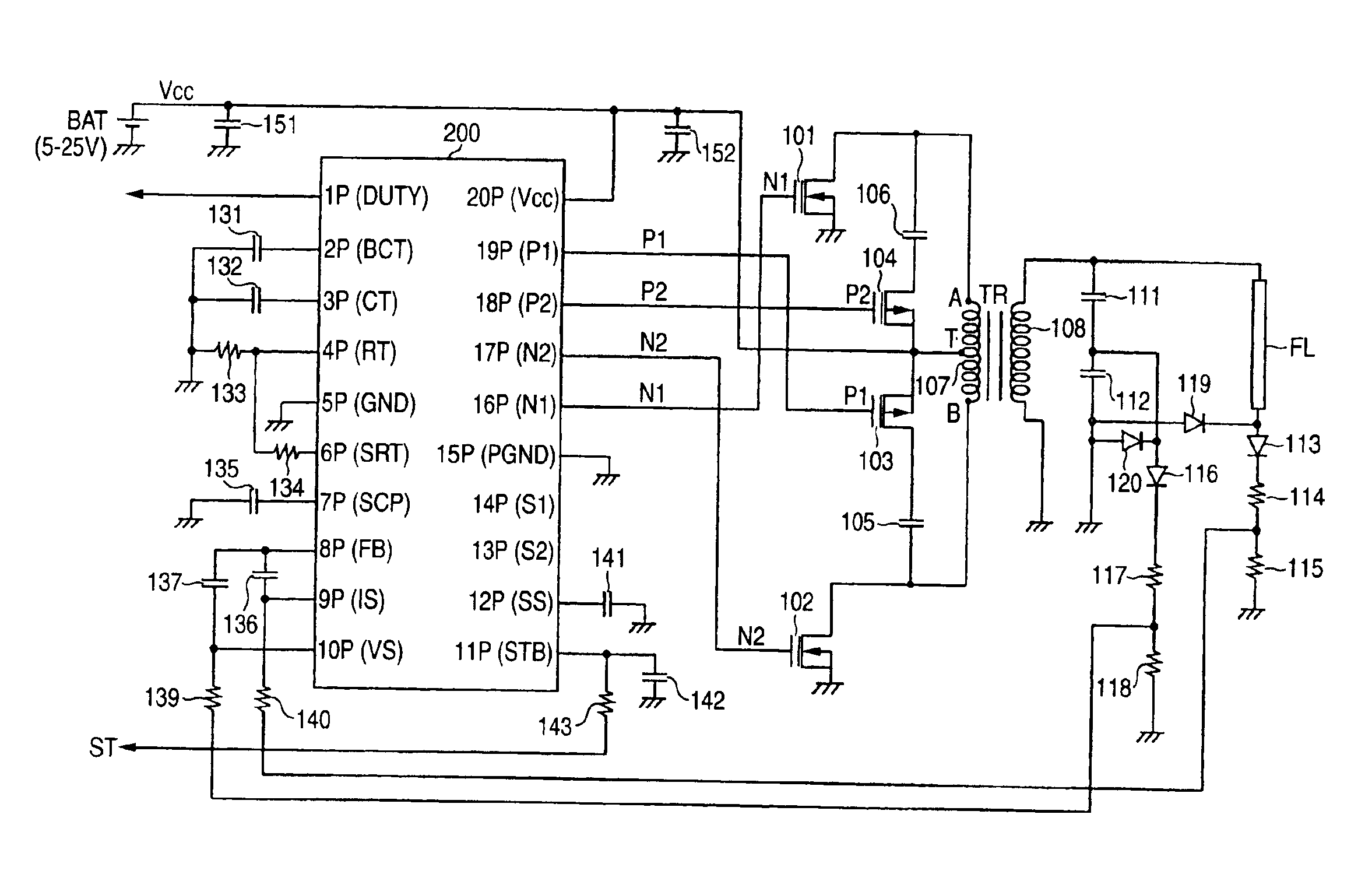
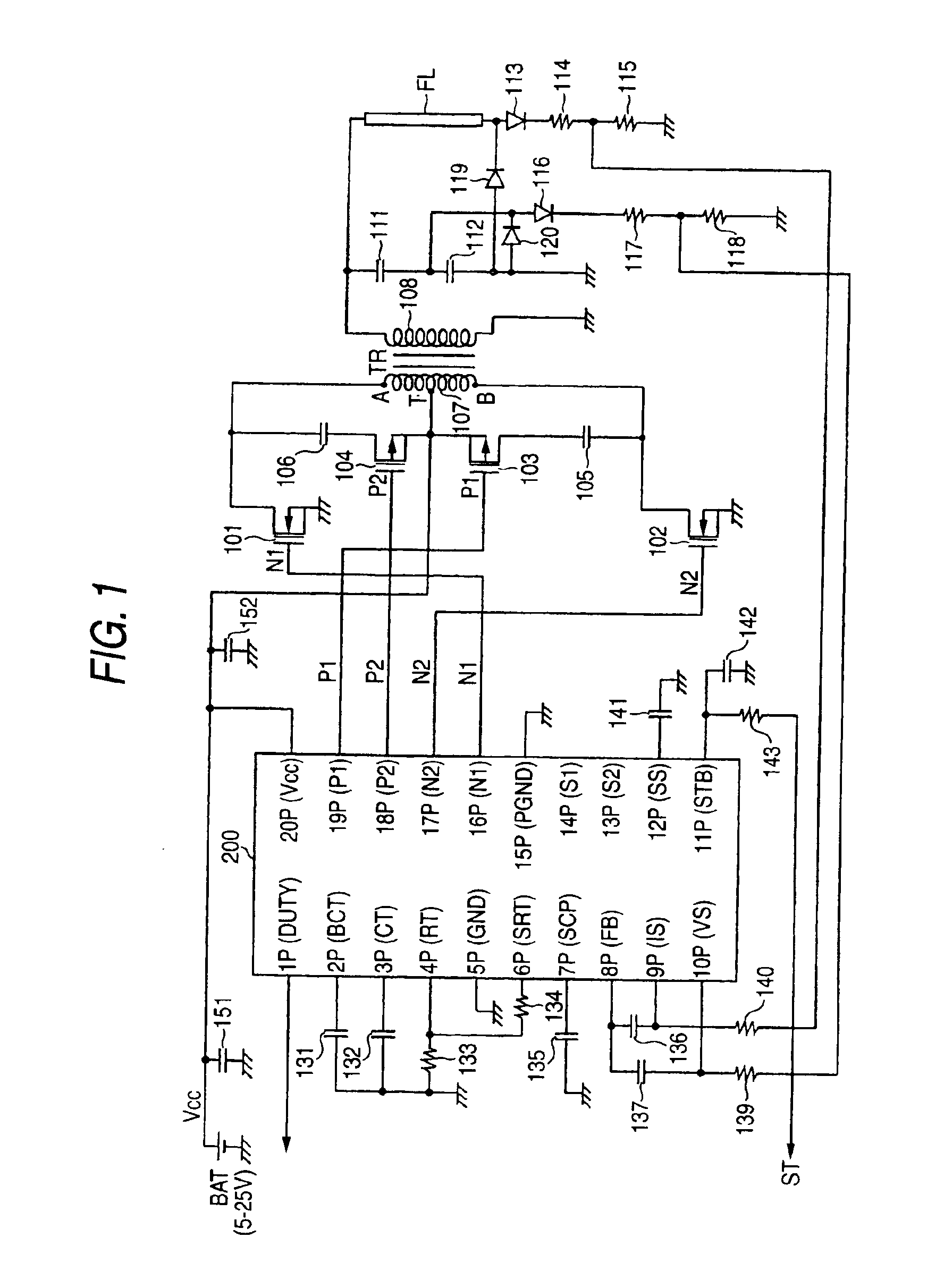
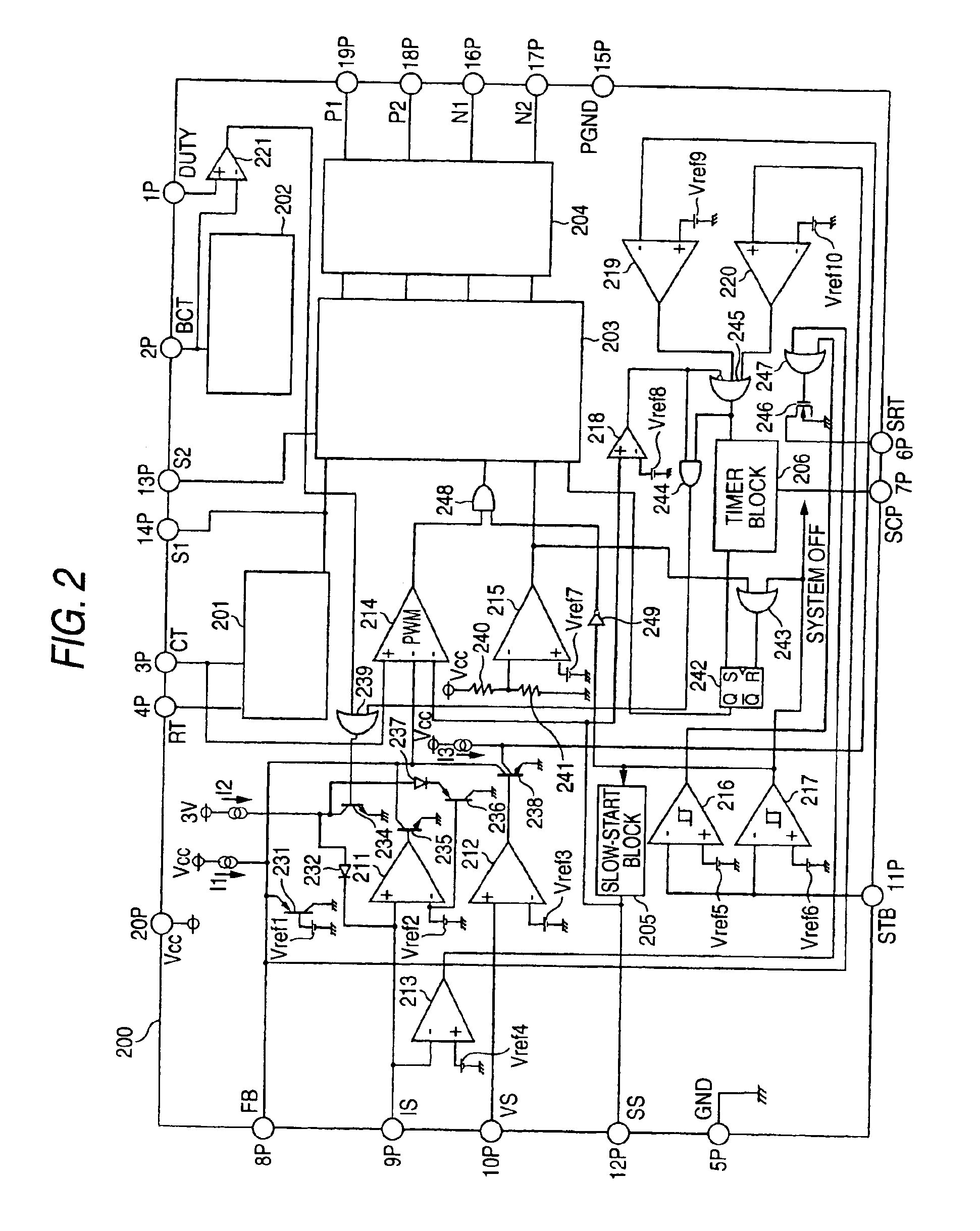
[0032]FIG. 1 is a view showing the entire configuration of an inverter of the embodiment of the invention which performs PWM control operation through use of an insulating transformer having a primary winding with a center tap and a secondary winding and through use of semiconductor switching circuits. FIG. 2 is a view showing the internal configuration of an IC for controlling the inverter.
[0033]In FIG. 1, a transformer TR is an insulating transformer having a primary winding 107 and a secondary winding 108 for supplying AC power to a load, wherein the primary winding 107 has a center tap T, one terminal A (hereinafter called a “first terminal”), and the other terminal B (hereinafter called a “second terminal”). A DC supply voltage ...
PUM
 Abstract
Description
Claims
Application Information