
Optical measurement instrument and optical measurement method

Inactive Publication Date: 2006-05-16
HITACHI LTD +1
View PDF17 Cites 23 Cited by
  • Summary
  • Abstract
  • Description
  • Claims
  • Application Information

AI Technical Summary

Benefits of technology

[0007]An object of the present invention is to provide an optical measurement system and an optical measurement method which is suitable for optically measuring a body to be inspected and easily obtaining an image of a desired item based on information obtained by the measurement.
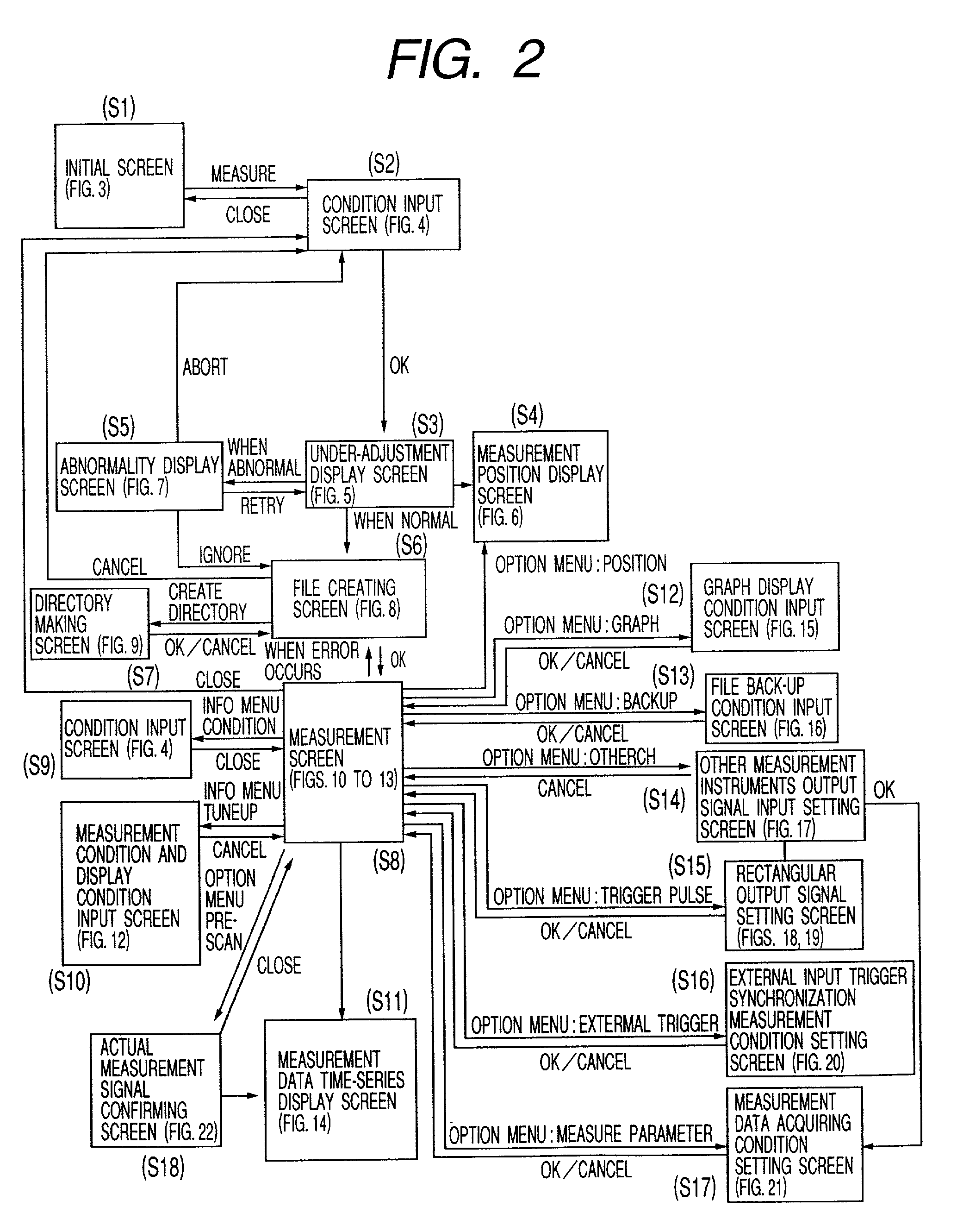
[0008]In order to attain the above object, in the present invention, measuring positions and a layout of optical fibers specific in the multi-channel optical measurement system are presented to an operator using a display portion. Further, by adding a function of changing the displayed layout corresponding to a measuring signal, it becomes easy to understand the status of the channels. Furthermore, in the present invention, a limited number of windows for inputting measurement conditions are displayed on the display portion, and measurement conditions in the next level hierarchy are displayed after completion of the inputting.

Problems solved by technology

In a multichannel optical measurement system, it is difficult to speedy detect a channel having a problem unless correspondence between actual measured positions and measured signals is shown to an operator operating the system.
In addition, there have been problems to cause serious results in the field of clinical treatment unless the operator inputs a large amount of measuring conditions before initiating the measurement.

Method used


Image

  • Optical measurement instrument and optical measurement method
  • Optical measurement instrument and optical measurement method
  • Optical measurement instrument and optical measurement method

Examples


Embodiment Construction

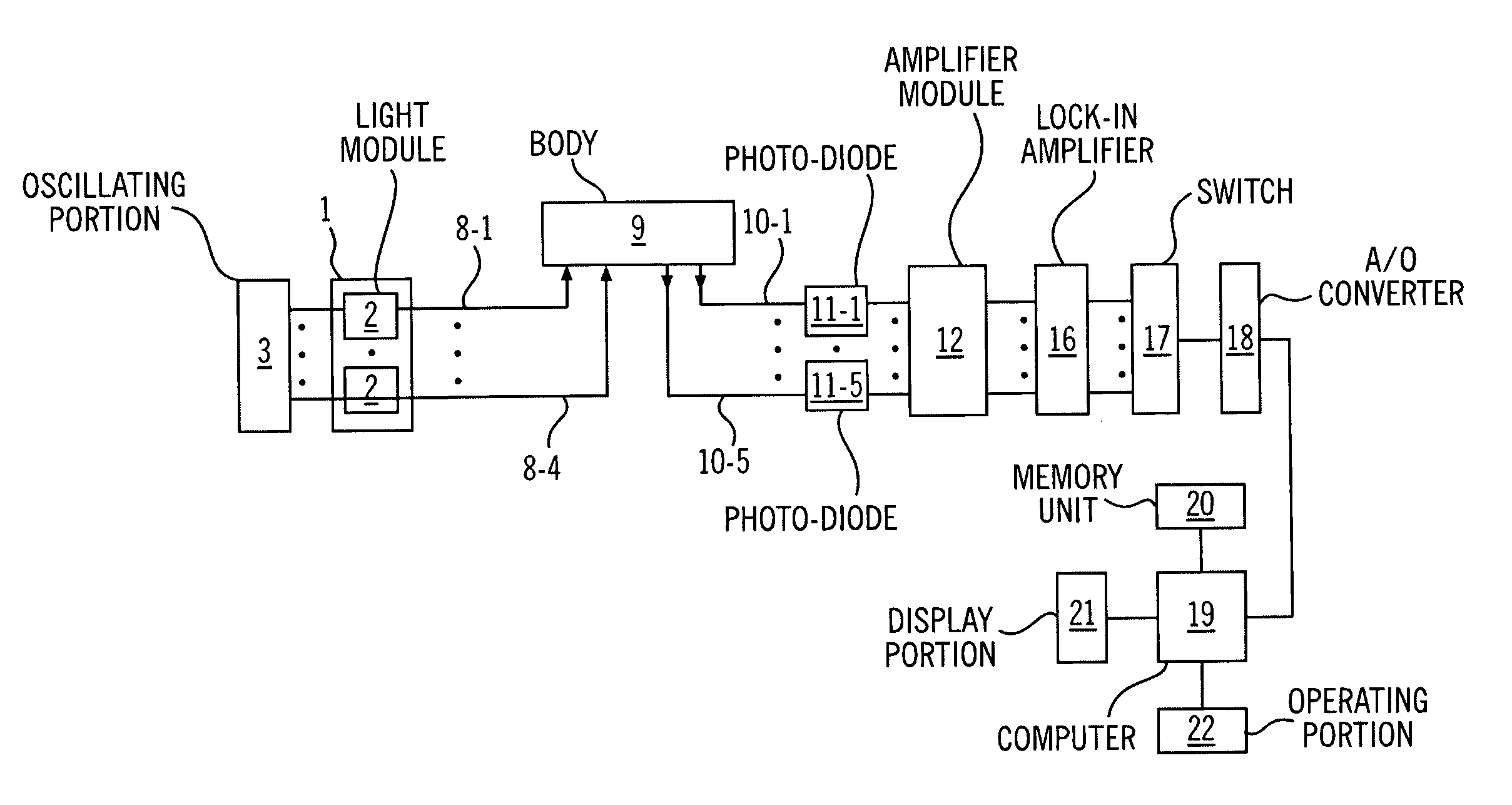
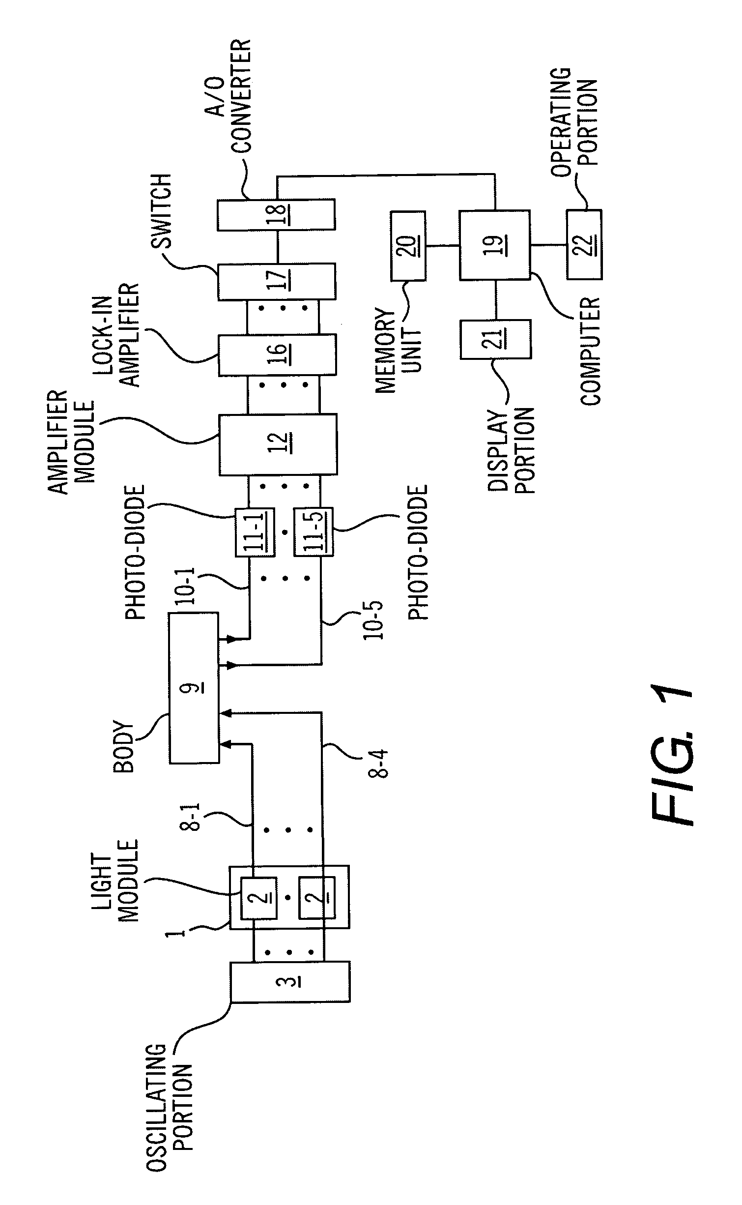
[0039]FIG. 1 is a block diagram showing the construction of the main portion of an embodiment of an optical measurement system to which the present invention is applied. The present embodiment is that light is irradiated, for example, on the skin of a head and then light penetrating into and scattered by the body is detected from the skin to image the inside of the cerebrum. In the embodiment, number of measurement channels, that is, number of measurement positions is 12. Of course, the object to be measured is not limited to a head, and the present invention can be applied to the other portions and to an object other than a biological body.

[0040]A light source portion 1 is composed of four light modules 2. Each of the light modules is composed of a plurality of semiconductor lasers each emitting light having a different wavelength within a wavelength band from visual to infrared, for example, two semiconductor lasers each emitting light having either of 780 nm or 830 nm wavelength....


PUM


Abstract

An optical measurement system for optically measuring a body to be inspected and obtaining an image of a desired item based on information obtained by the measurement includes means for displaying a number of measurement points, means for indicating a light irradiation position and a light detecting position and means for displaying a measurement position and a state of allocating a number to the measurement position. The system further includes means for displaying measuring time sequence data, means for setting a condition of acquiring data, means for displaying a status of acquiring the data, means for instructing control of measurement and means for marking a mark at a position measuring time sequence data.

Description

BACKGROUND OF THE INVENTION[0001]The present invention relates to an optical measurement system and an optical measurement method, and particularly, to an optical measurement system which is suitable for optically measuring the inside of a biological body and imaging the inside of the biological body based on information signals obtained by the measurement.[0002]A technology of easily measuring the inside of a biological body without affecting any ill effect on the biological body is desired in the field of clinical treatment. Measurement using light is very effective for this desire. The first reason is that oxygen metabolism inside the biological body corresponds to a concentration of specific pigments (hemoglobin, cytochrome a a3, myoglobin and so on), that is, light absorbents in the biological body, and the concentration of the pigments can be obtained from an amount of absorbed light (in a wavelength band from visible light to near-infrared light). The second reason is that li...

Claims


Application Information

Patent Timeline
IPC IPC(8): G01C17/00G01N21/27A61B5/00A61B5/145A61B5/1455A61B10/00G01N21/17G01N21/35G01N21/359G01N21/49
CPCA61B5/14553G01N21/49A61B5/7435A61B5/0042
Inventor MAKI, ATSUSHIYAMASHITA, YUUICHIYAMAMOTO, TSUYOSHIKOIZUMI, HIDEAKI
Owner HITACHI LTD
Learn More