Agricultural disc harrow and method

a disc harrow and disc technology, applied in the field of disc harrow, can solve the problems of difficult rotation of the disc, impracticality of the feature, and inability to rotate the disc, so as to reduce the resistance and reduce the diameter

Inactive Publication Date: 2006-05-23
BOLLICH GERALD
View PDF37 Cites 32 Cited by
  • Summary
  • Abstract
  • Description
  • Claims
  • Application Information

AI Technical Summary

Problems solved by technology

However, uniformity has proven to be elusive requiring multiple rows of disc gangs and breakers often set at oblique angles.
Furthermore, farmers find that they must often rotate their discs to compensate for wear or exchange them when damaged.
In cases where single disc mountings are utilized the angle of attack may be varied but conventional wisdom and the cost of providing individual, adjustable acute angulations tends to make this feature impractical.
Since it is desirable to maintain a consistent depth of spindle, this act becomes a time consuming chore.
Disc depth and angle adjustment coupled with disc wear has long been a costly problem for farmers due to the time required to set both the depth and angulations of each disc and or change-out worn discs.
Whereas inline disc gangs towed or attached in a three-point hitch arrangement located perpendicular to the direction of travel are used for back and forth field cultivation, the latter arrangement inevitably leaves irregular soil patterns near each end of the disc gangs.
In such cases rotating the soil is not only unnecessary but also detrimental by exposing the vital nutrients to the elements of wind and rain.

Method used


Image

  • Agricultural disc harrow and method
  • Agricultural disc harrow and method
  • Agricultural disc harrow and method

Examples


first embodiment

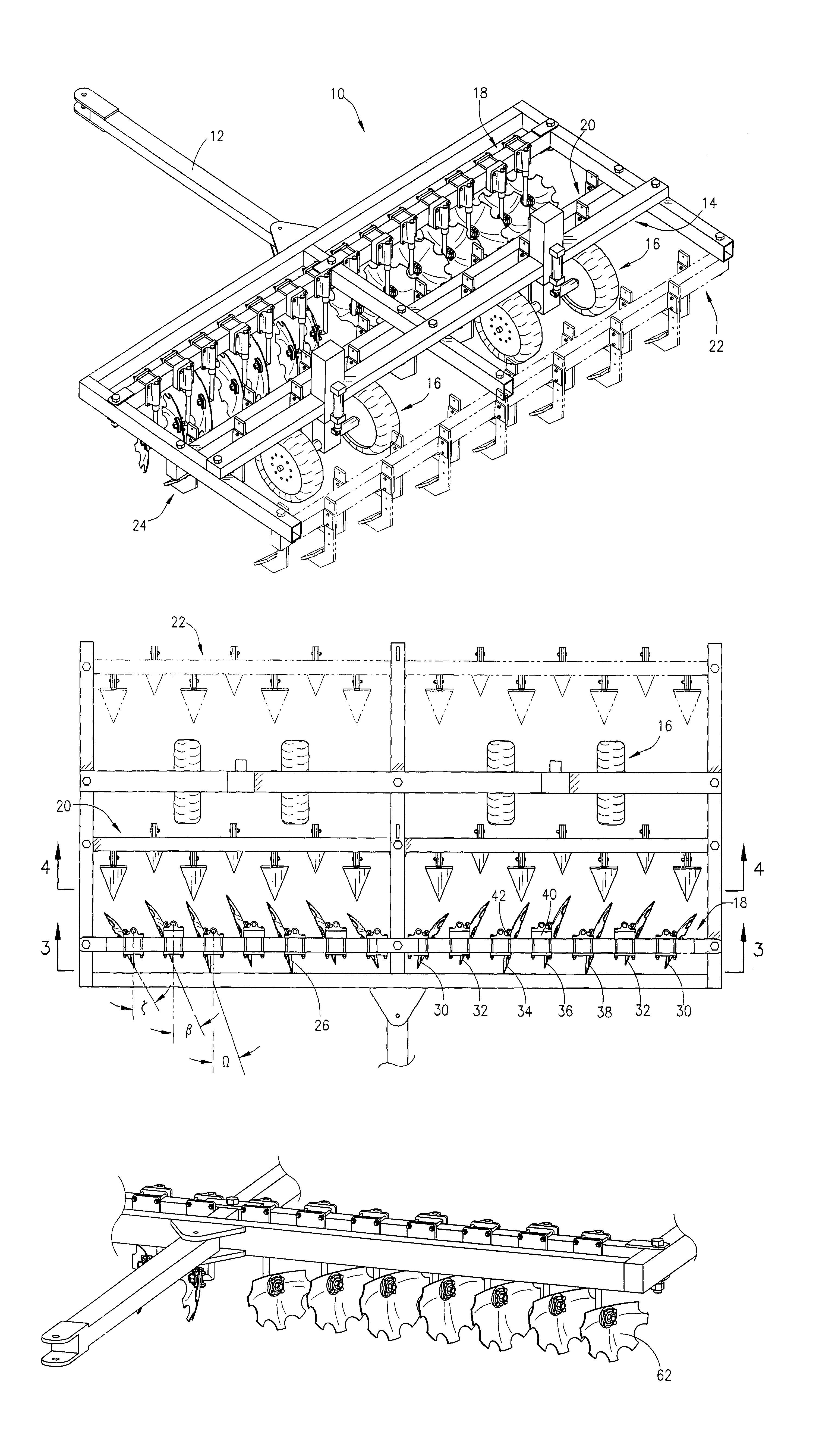
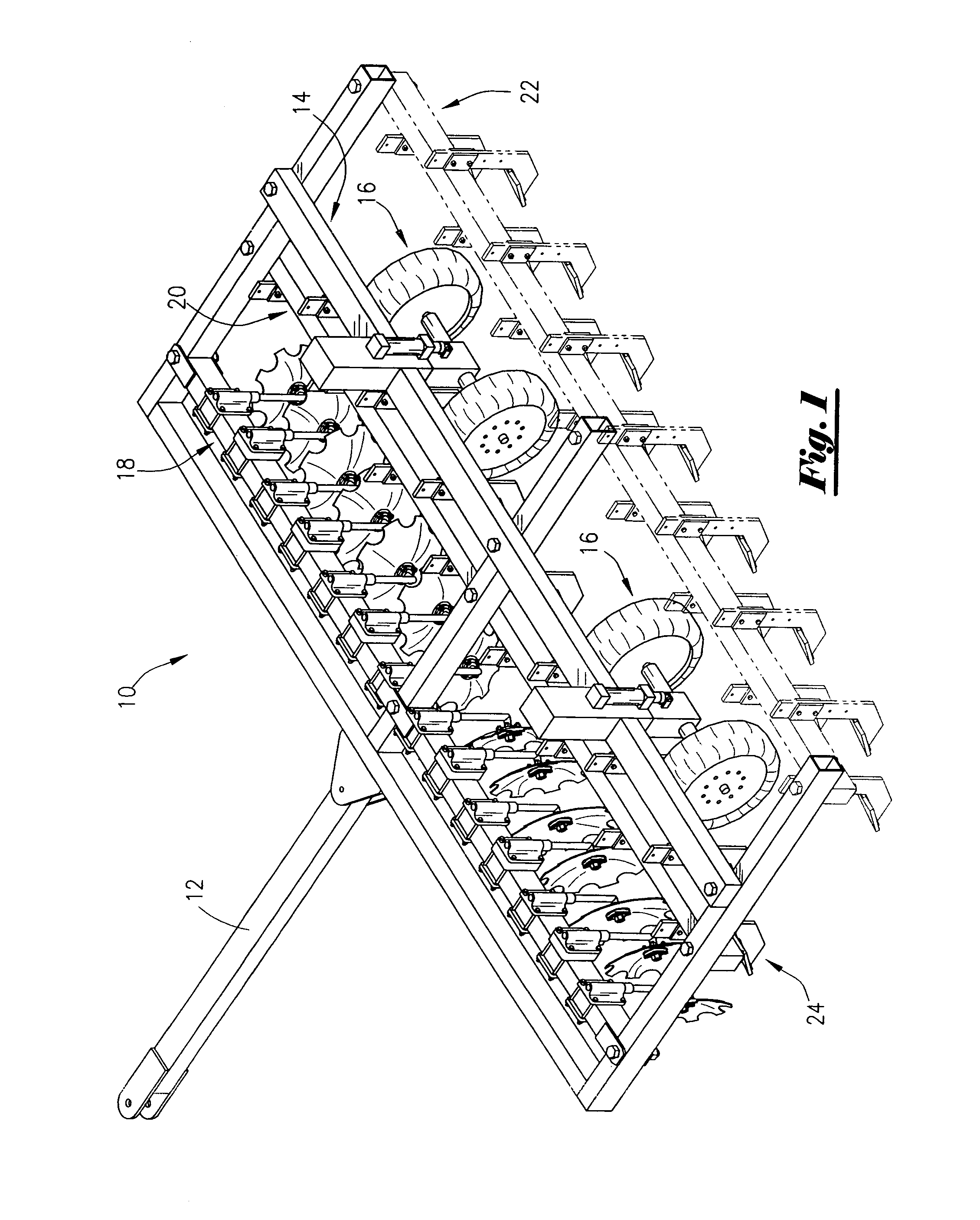
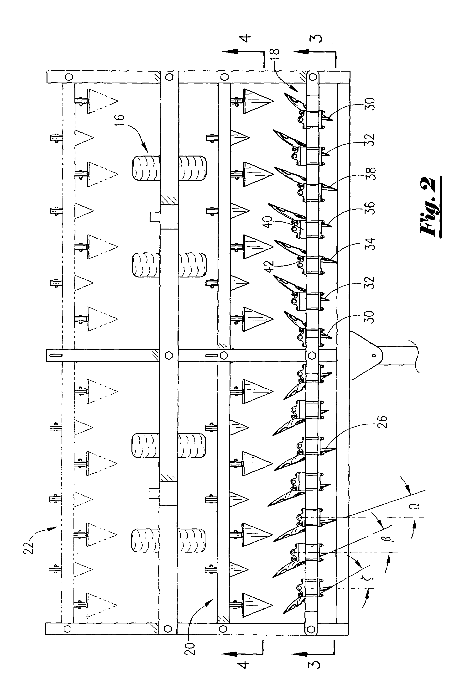
[0025]Looking at the disc harrow assembly 10 shown in FIG. 1, it can be seen that the assembly is a towed implement including a pivotal tow tongue 12 and a frame assembly 14 supported by a pair of hydraulically retractable wheel assemblies 16 with the leading tool bar assembly 18 being perpendicular to the tongue 12 that includes a plurality of rotatable discs. The assembly 10 is further provided with a secondary tool bar assembly 20 located directly behind the leading tool bar 18 and in front of the wheel assemblies 16 fitted with a plurality of vertical breaker bar assemblies 24. An optional third tool bar assembly 22 may be attached to the disc harrow 10 frame assembly 14 behind the hydraulically retractable wheel assemblies 16 if desired. Turning now to FIG. 2 we see that the primary or leading tool bar assembly 18 with its plurality of rotatable discs 26 is arranged in an usual manner with one group facing one direction and the second group facing the opposite direction. Howeve...

second embodiment

[0031]In any case, the leveler assembly 48 and the smoothing plate assembly so are mounted to the second embodiment in such a manner the leveler assembly 48 and the smoothing plate assembly 50 are flexible relative to the disc harrow assembly 46 but remain in a sufficiently ridged connection so as to allow the leveler and smoother plate assemblies 48, 50 to be lifted by the wheel assemblies 16 as shown in FIG. 11.

[0032]The combination assembly 60 as depicted in FIG. 12a may be duplicated and hinged to each side of the assembly 60 as shown in FIG. 13. The wing assemblies 60a and 60b may be hydraulically lifted for transport in the typical manner currently employed by the art.

[0033]Looking now at FIG. 14 we see another innovation in that the leading disc assembly 18 may be replaced with non-rotatable half discs made from reconditioned broken or worn discs. It has been found that the disc harrow assemblies 10 or 46 are capable of utilizing these half discs 62 to cut the soil in some ca...


PUM


Abstract

An agricultural implement consisting primarily of a towed frame supported on retractable wheels, the frame having a plurality of independently adjustable spindles for setting height and angle of attack for various size rotatable discs. Each disc is staggered to reduce resistance and clogging. Each group of discs further includes descending diameter discs at each end with the angle of attack increasing with each decrease in diameter while spacing between the discs decreases as the diameters are reduced. The implement further including harrow teeth or picks located at strategic points adjacent the discs to ensure uniform soil disruption, the disc assembly being convertible from single gang to double gang assembly and may include conventional harrow teeth sets and or unique soil leveler attachments.

Description

FIELD OF THE INVENTION[0001]This invention relates generally to a disc harrow towed by a farm tractor or the like, having retractable wheels for transport and more particularly to improvements to such disc harrows including the addition of breaker bars at strategic points and a drag-type soil leveler.GENERAL BACKGROUND[0002]In the preparation of soil for planting, a disc harrow, defined as a harrow equipped with a series of sharp metal discs set on edge or at an angle on one or more axles, is frequently used as an implement. Harrows have multiple gangs of discs located independently or in groups of two or more for turning and breaking the soil. These discs are generally arranged in a wide range of configurations designed to provide maximum soil disruption over as large an area as possible in a single pass. Even so, some earth remains unbroken, including large clumps or clods. In some instances picks or breaker bars are used in combination with the disc sets or as a secondary operati...

Claims


Application Information

Patent Timeline
Patent Type & Authority Patents(United States)
IPC IPC(8): A01B49/02
CPCA01B21/086A01B49/02A01B31/00
Inventor BOLLICH, GERALD
Owner BOLLICH GERALD
Why Eureka
Try Eureka