Low profile horizontally polarized sector dipole antenna

a dipole antenna and low-profile technology, applied in the field of antennas, can solve the problems of complex assembly of the antenna, small tolerances for such antennas, design and manufacture of sector h-pol antennas,

Inactive Publication Date: 2006-05-23
SUPERPASS
View PDF6 Cites 27 Cited by
  • Summary
  • Abstract
  • Description
  • Claims
  • Application Information

AI Technical Summary

Problems solved by technology

However, at present, the design and manufacture of sector H-POL antennas still tends to pose certain challenges.
The manufacturing tolerances for such antennas tend to be quite small.
Assembly of this antenna tends to be complicated.
While certain sector H-POL antennas are available on the market, they tend to be bulky and / or expensive.
While adjusting the H-Plane radiation pattern of such dipole antennas is generally known, there currently does not appear to be an effective way to broaden the E-Plane beamwidth of such dipole antennas.

Method used


Image

  • Low profile horizontally polarized sector dipole antenna
  • Low profile horizontally polarized sector dipole antenna
  • Low profile horizontally polarized sector dipole antenna

Examples


Embodiment Construction

[0024]The description which follows, and the embodiments described therein are provided by way of illustration of an example, or examples of particular embodiments of principles and aspects of the present invention. These examples are provided for the purposes of explanation and not of limitation of those principles of the invention. In the description that follows, like parts are marked throughout the specification and the drawings with the same respective reference numerals.

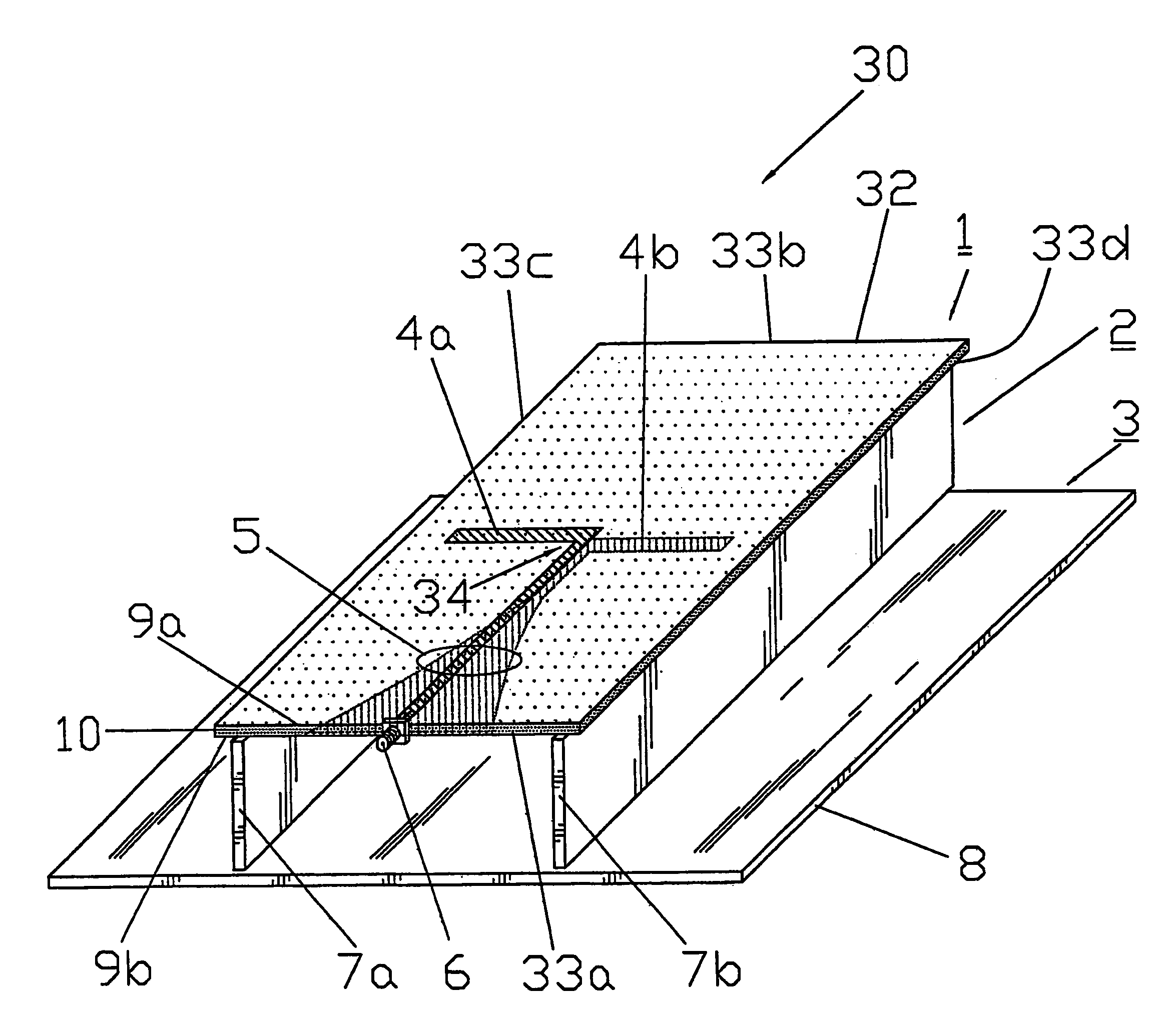
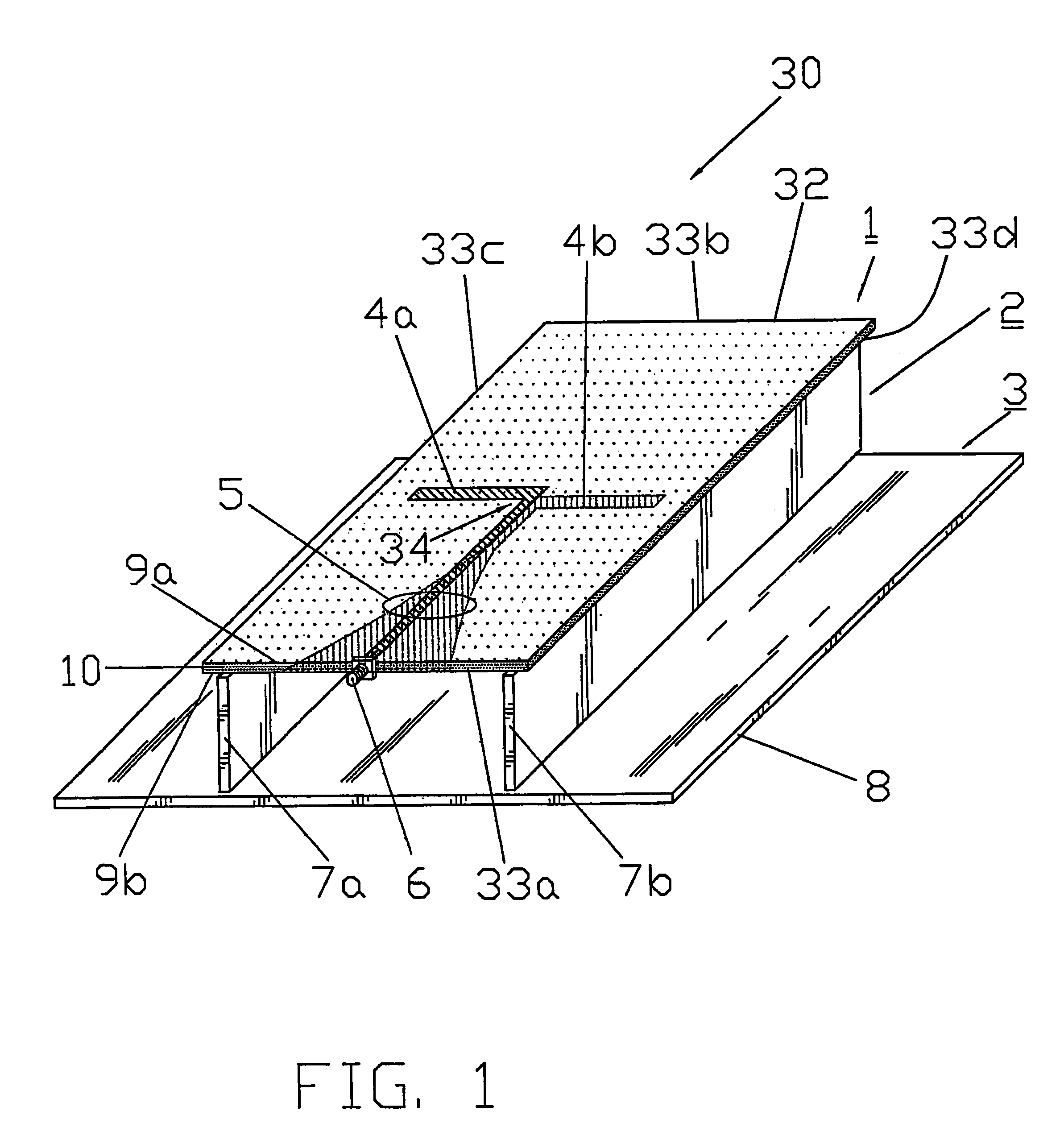
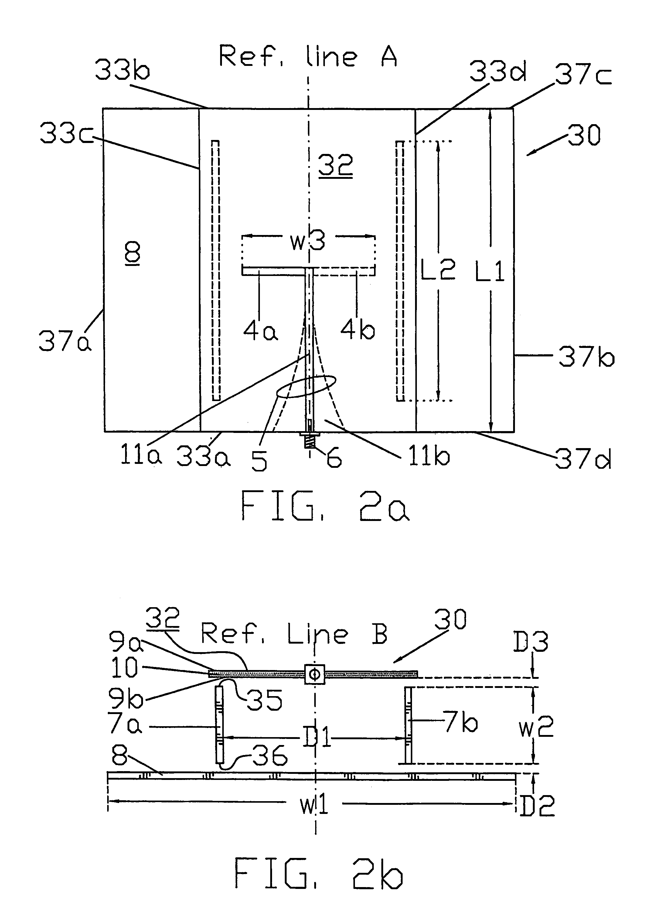
[0025]Referring to FIGS. 1, 2a and 2b, there is a shown a single element H-POL sector dipole (“HSD”) antenna designated generally with reference numeral 30. The HSD antenna 30 is horizontally polarized, and may be used to provide a relatively broad, E-Plane beamwidth, as will be described in greater detail below. As shown in FIG. 2a, the HSD antenna 30 is a generally symmetrical structure having three main assemblies—more specifically, first, second and third assemblies 1, 2 and 3, respectively. The first and s...


PUM


Abstract

The present invention relates generally to the field on antennas and more specifically, to a low profile horizontally polarized sector antenna. The antenna includes a printed circuit board that has a dielectric substrate provided with a pair of first and second opposed faces and at least one dipole element formed on the dielectric substrate. The at least one dipole element has a pair of first and second, oppositely extending, dipole arms. The first dipole arm is formed on the first face of the dielectric substrate and the second dipole arm is formed on the second face thereof. The at least one dipole element has a width W corresponding to the span between the first and second dipole arms. The printed circuit board is also provided with a feed network that is operatively connected to the at least one dipole element. The antenna further includes a pair of conductive boards mounted to the dielectric substrate to stand proud of the second face thereof. The conductive boards are spaced from each other a distance D. The distance D is greater than the width W. The distance D is selected to obtain an E-Plane beamwidth for the antenna ranging from about 90 degrees to about 240 degrees. The antenna also has a ground plane that is operatively connected to the pair of conductive boards.

Description

FIELD OF INVENTION[0001]The present invention relates generally to the field on antennas and more specifically, to a low profile horizontally polarized sector antennas.BACKGROUND OF THE INVENTION[0002]In the area of wireless communication systems, the need to increase capacity while minimizing possible interference with existing vertically polarized systems, has created a strong demand for horizontally polarized (“H-POL”) antennas.[0003]Directional H-POL antennas tend to be relatively easy to design and may be manufactured cost effectively. However, at present, the design and manufacture of sector H-POL antennas still tends to pose certain challenges. More specifically, conventional sector H-POL antennas are usually configured as waveguide slot antennas. Manufacturing of these antennas tends to be an involved process entailing, among other things, the formation of a waveguide and the cutting of a slot into the waveguide. The manufacturing tolerances for such antennas tend to be quit...

Claims


Application Information

Patent Timeline
Patent Type & Authority Patents(United States)
IPC IPC(8): H01Q9/28
CPCH01Q5/00H01Q9/285H01Q5/28H01Q21/08H01Q5/25H01Q21/062
Inventor CHEN, XI FANJIANG, GUOZHONG
Owner SUPERPASS
Why Eureka
Try Eureka