Laser irradiation device and image recorder

a laser irradiation device and laser beam technology, applied in the direction of laser details, printing, electrical equipment, etc., can solve the problems of increasing the energy of the laser beam, grating light valves to be damaged, etc., to reduce thermal damage to grating light valves, efficient and stable laser beam application, effect of reducing thermal damag

Inactive Publication Date: 2006-05-23
DAINIPPON SCREEN MTG CO LTD
View PDF14 Cites 2 Cited by
  • Summary
  • Abstract
  • Description
  • Claims
  • Application Information

AI Technical Summary

Benefits of technology

[0018]The use of the laser beam having the peak wavelength ranging from 800 nm to 820 nm allows efficient and stable application of the energy of the laser source to the recording medium, and reduces thermal damages to the Grating Light Valve™.
[0019]It is therefore an object of the present in

Problems solved by technology

Furthermore, insufficient reflectance of Grating Light Valve™ leads to accordingly more energy of the laser beam a

Method used


Image

  • Laser irradiation device and image recorder
  • Laser irradiation device and image recorder
  • Laser irradiation device and image recorder

Examples


Embodiment Construction

[0037]

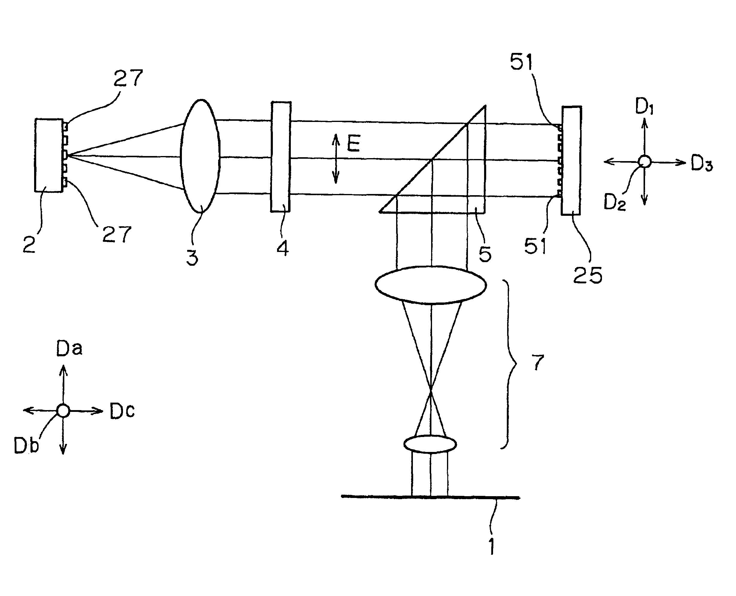
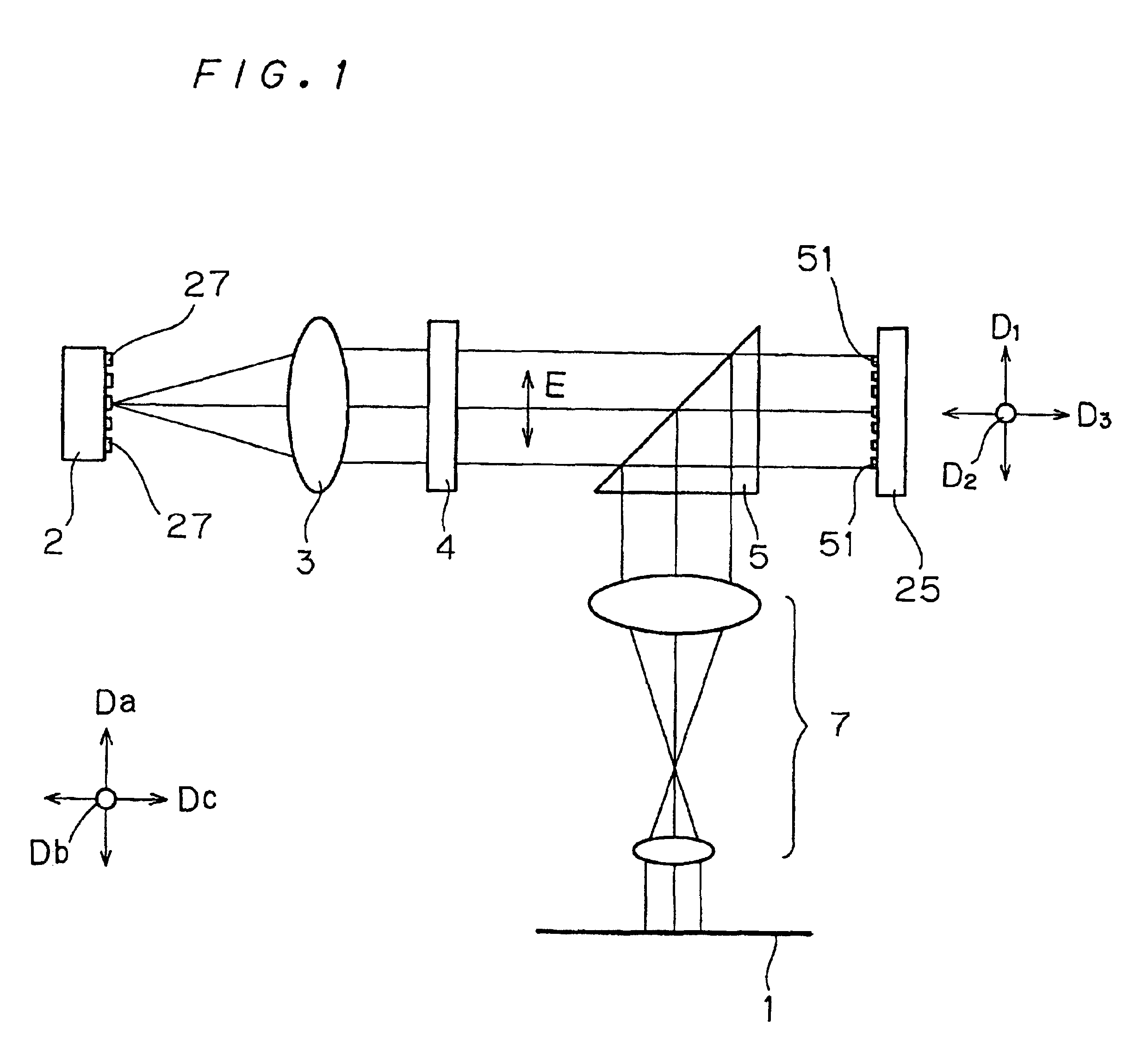
[0038]FIG. 1 is a schematic view of a laser irradiation device according to a first preferred embodiment of the present invention.

[0039]The laser irradiation device of FIG. 1 is used in an image recorder for imaging a laser beam on a to-be-irradiated medium 1 such as photosensitive and heat-sensitive materials to record an image thereon. The laser irradiation device of FIG. 1 comprises: a laser source 2; Grating Light Valve™25; an illumination optical system 3 for illuminating Grating Light Valve™25 with a laser beam emitted from the laser source 2; an imaging optical system 7 for imaging the laser beam modulated by Grating Light Valve™25 on the medium 1; a phase plate (half wave plate) 4 for rotating the polarization of the laser beam emitted from the laser source 2 by 90 degrees; and a prism 5 for deflecting the direction of the laser beam modulated by Grating Light Valve™25 by 90 degrees.

[0040]A semiconductor laser known as a bar laser (broad area semiconductor laser) havin...


PUM


Abstract

A laser source emits a laser beam having a peak wavelength within the range from 800 nm to 820 nm. The laser beam emitted from the source passes through an illumination lens, and then impinges on a Grating Light Valve™. The light valve splits the laser beam into a multiplicity of light beams, modulates the multiplicity of light beams in response to image signals, and produces zero-order diffracted signal beams. The zero-order diffracted beams pass through an imaging lens, and are imaged on a recording medium wrapped on the surface of a drum.

Description

BACKGROUND OF THE INVENTION[0001]1. Field of the Invention[0002]The present invention relates to a laser irradiation device for irradiating a medium with a laser beam modulated by Grating Light Valve, and an image recorder for recording an image on a recording material using a laser beam modulated by the laser irradiation device.[0003]2. Description of the Background Art[0004]Grating Light Valve is such a light valve that thousands of narrow, laterally arranged reflecting plates (or ribbons) are moved using an electrostatic force to cause diffraction which in turn is used to modulate a light beam. The Grating Light Valve functions as a plane mirror when all of the ribbons are coplanar, and as a reflective diffraction grating when alternate ones of the ribbons are moved down a distance equal to one quarter of the wavelength of a laser beam. The “Grating Light Valve” or “GLV” is trademarked and marketed by Silicon Light Machines (Sunnyvale, Calif., U.S.A.). Grating Light Valve™ is con...

Claims


Application Information

Patent Timeline
IPC IPC(8): B41J2/47H04N1/028H04N1/06
CPCH04N1/06H04N1/0281
Inventor TAMAKI, EIICHI
Owner DAINIPPON SCREEN MTG CO LTD
Why Eureka
Try Eureka