Zoom lens barrel

a zoom lens and barrel technology, applied in the direction of mountings, instruments, printing, etc., can solve the problem that the lens hood is not suitably used, and achieve the effect of maintaining desired optical characteristics and miniaturizing its siz

Active Publication Date: 2006-05-23
OM DIGITAL SOLUTIONS CORP
View PDF13 Cites 18 Cited by
  • Summary
  • Abstract
  • Description
  • Claims
  • Application Information

AI Technical Summary

Benefits of technology

[0011]A zoom lens barrel of the present invention is characterized in that it can maintain desired optical characteristics, can move a plurality of lens groups in a different direction or in a different amount in focusing, and moreover can miniaturize its size.

Problems solved by technology

Accordingly, although the lens hood is formed symmetrically up and down and right and left, the lens hood is not suitably used when it is rotated in, for example, an oblique direction.

Method used


Image

  • Zoom lens barrel
  • Zoom lens barrel
  • Zoom lens barrel

Examples


first embodiment

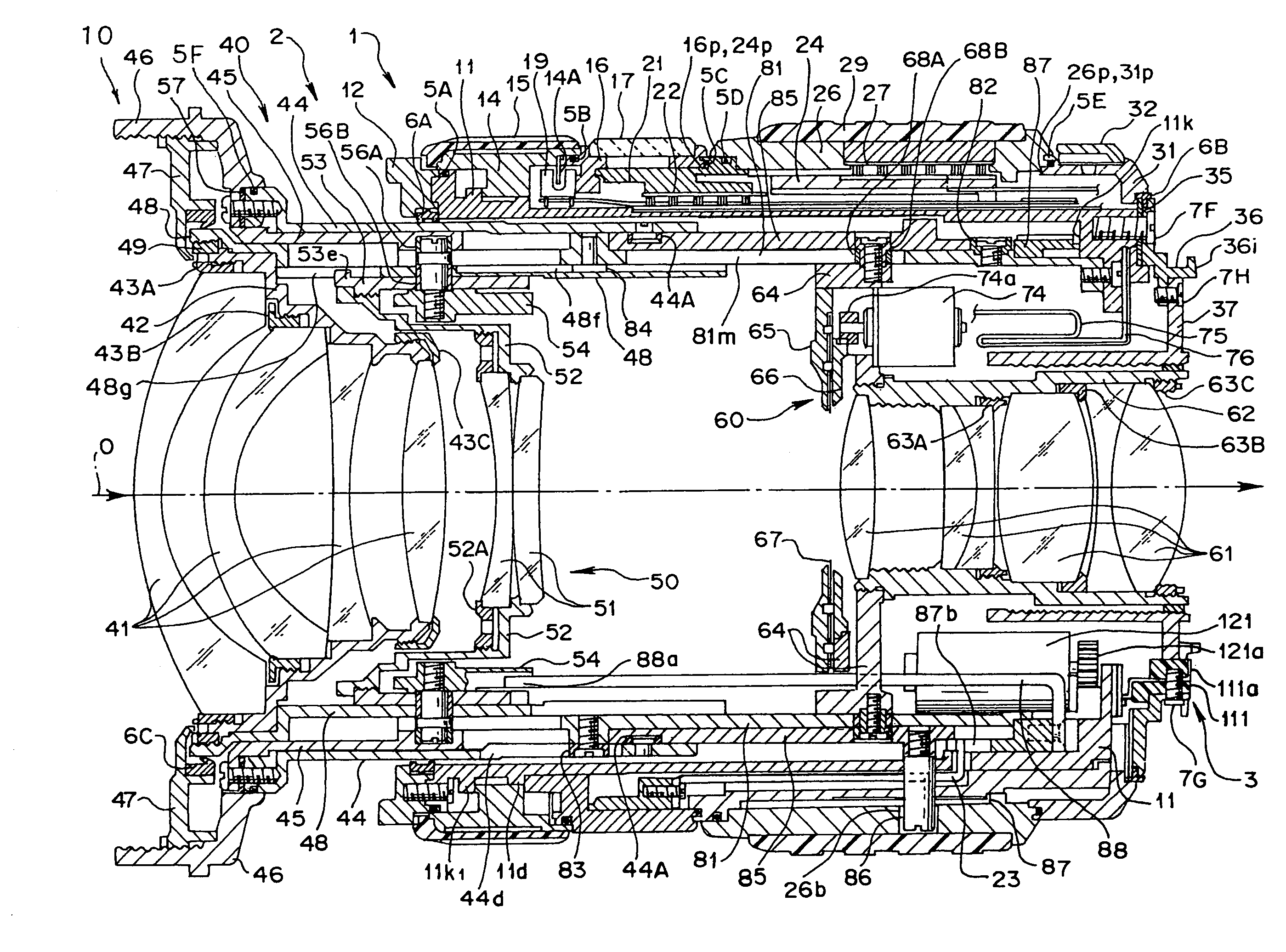
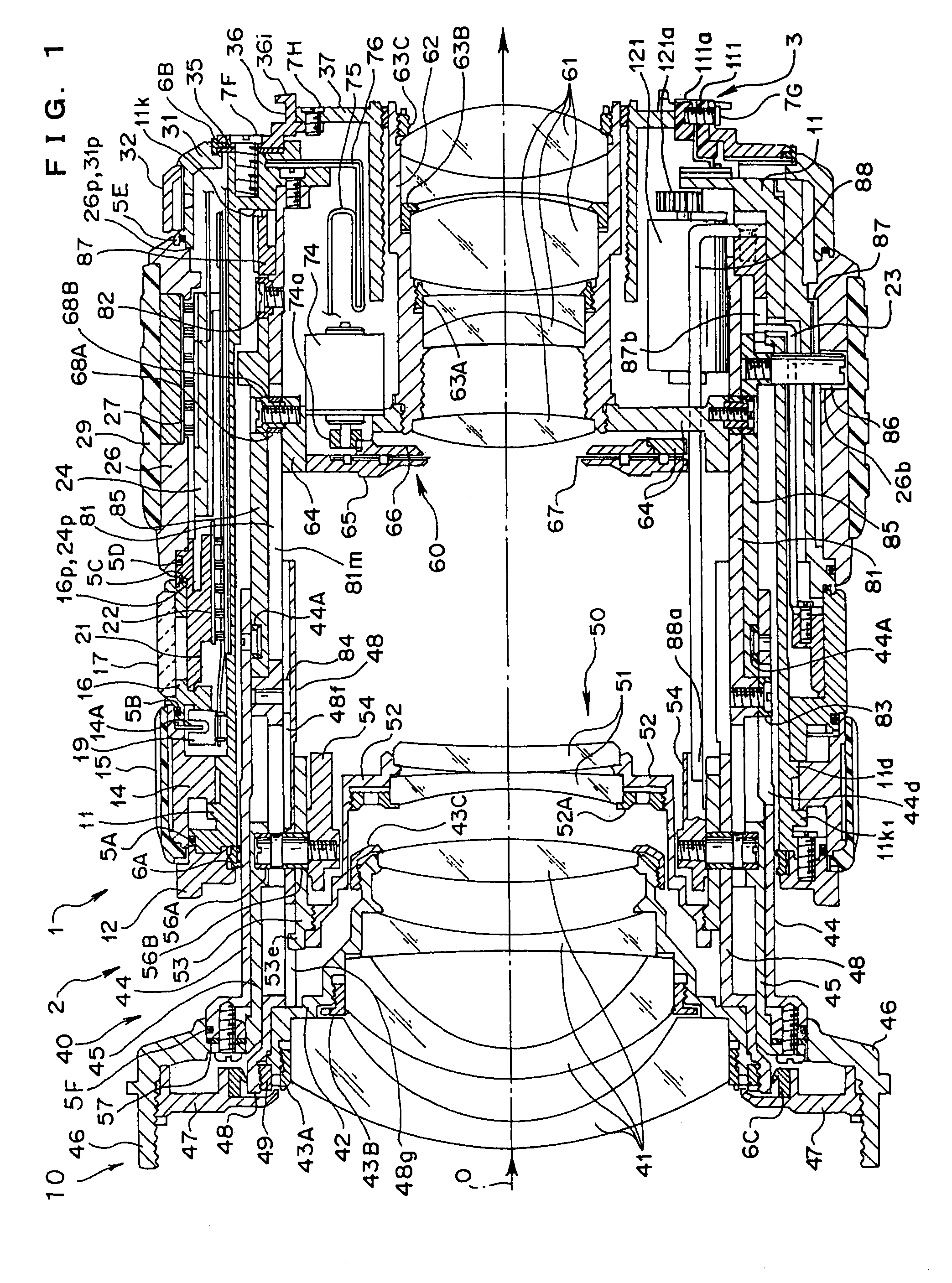
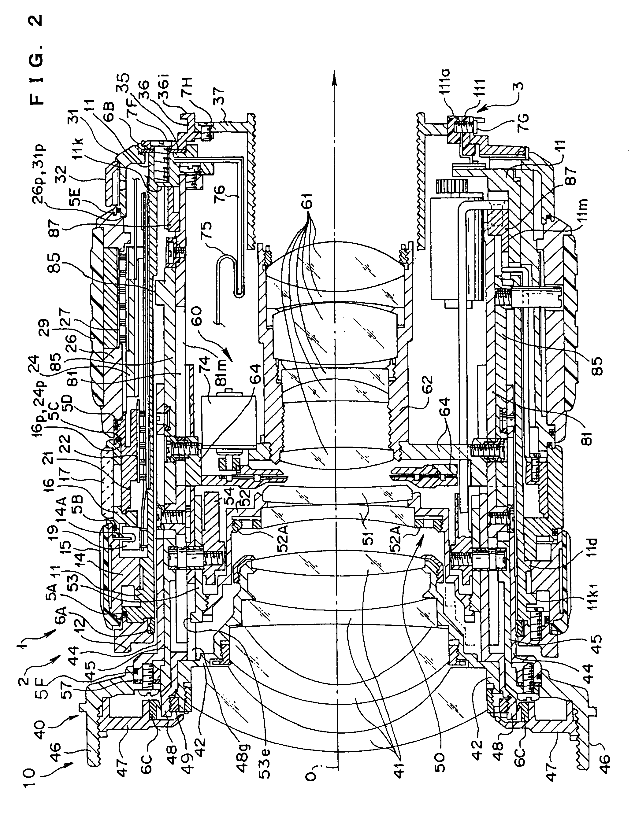
[0033]A lens barrel as the present invention will be explained using FIGS. 1 to 13.

[0034]FIG. 1 is a sectional view of the lens barrel on an optical axis when it is in a wide state as well as in an infinite focusing state. FIG. 2 is a sectional view of the lens barrel on the optical axis when it is in a telescopic state and in the infinite focusing state. FIG. 3 is an exploded perspective view of a part of an exterior unit constituting the lens barrel, and FIG. 4 is an exploded perspective view of another part of the exterior unit constituting the lens barrel. FIG. 5 is an exploded perspective view of a part of an optical unit constituting the lens barrel, and FIG. 6 is an exploded perspective view of another part of the optical unit constituting the lens barrel. FIG. 7 is a perspective view of a control unit constituting the lens barrel when it is viewed from an image forming side (rear side). FIG. 8 is a developed view of a lens barrel control FPC constituting the control unit. FI...

second embodiment

[0153]FIGS. 15 to 17 show the present invention, wherein FIG. 15 is a sectional view along an optical axis showing a zoom lens barrel when a zoom position is located at a wide end and a focus position is located at infinity, FIG. 16 is a sectional view along the optical axis showing the zoom lens barrel when the zoom position is located at a telescopic end and the focus position is located at infinity, and FIG. 17 is a diagrammatic view in which a vertical axis shows the amounts of movement of respective lens groups in an optical axis direction in a zooming operation and a focusing operation, and a lateral axis shows a zoom position.

[0154]Note that, in the second embodiment, only the portions relating to the present invention will be mainly explained, and the explanation of the general arrangement, and the like of the zoom lens barrel will be appropriately omitted.

[0155]Further, in the zoom lens barrel 201, an object side (left side in FIGS. 15 and 16) is called a front side, and th...


PUM


Abstract

A zoom lens barrel comprises an exterior unit, which mainly forms an exterior portion, an optical unit having an image pickup optical system built therein, and a control unit and can be detachably mounted on a single-lens reflex camera. The optical unit includes first and second group lenses as the image pickup optical system, which can move forward and rearward in zooming and focusing, and a third group lens which can move forward and rearward in zooming. Particularly, in focusing, a first group lens holding frame for holding the first group lens and a second group lens holding frame for holding the second group lens are driven forward and rearward in a different amount in an optical axis direction through a cam follower and two cam grooves by driving a focus ring in rotation, thereby focusing is executed. The lens barrel can cope with a forward / rearward movement required in zooming and focusing and can be reduced in size.

Description

[0001]This application claims benefit of Japanese Applications No. 2003-427953 filed in Japan on Dec. 24, 2003 and No. 2004-326873 filed in Japan on Nov. 10, 2004 the contents of which are incorporated by this reference.BACKGROUND OF THE INVENTION[0002]1. Field of the Invention[0003]The present invention relates to a structure of a zoom lens barrel capable of executing focusing.[0004]2. Related Art Stament[0005]Image-pickup apparatuses such as a camera, an electronic camera, and the like have a lens barrel for holding an image pickup lens. In particular, when the image pickup lens is a lens capable of executing zooming, the lens barrel is called a zoom lens barrel.[0006]An image pickup lens held by the zoom lens barrel is generally divided into a plurality of lens groups such as a lens group for mainly executing focusing, a lens group for mainly executing zooming, and the like depending on the optical functions born thereby. More specifically, there is an example in which a lens gro...

Claims


Application Information

Patent Timeline
Patent Type & Authority Patents(United States)
IPC IPC(8): G02B15/14G02B7/02G03B17/00G03B17/04G02B7/04G02B7/10
CPCG02B7/102
Inventor HAYASHI, SHIGEOAKITA, HIDENORI
Owner OM DIGITAL SOLUTIONS CORP
Why Eureka
Try Eureka