Subsurface fibre optic cable network installation

a fibre optic cable and subsurface technology, applied in the direction of cables, cables laying apparatus, instruments, etc., can solve the problems of prohibitively high cost, inconvenient installation, method that cannot work in concrete materials, etc., and achieve the effect of high rigidity and sufficient rigidity

Inactive Publication Date: 2006-05-23
TERASPAN NETWORKS
View PDF30 Cites 51 Cited by
  • Summary
  • Abstract
  • Description
  • Claims
  • Application Information

AI Technical Summary

Benefits of technology

[0031]A generally rigid frame such as a rigid wire loop may be provided to support the cable loops. By “rigid” is meant having sufficient rigidity to protect a cable loop from damage. A high degree of rigidity is not necessarily required. The frame has generally the same configuration as the cable loops, and is joined to the base either before or after the loops are wound about the base. The combined looped region of cable and wire frame are then released from the winder for burial. The attached wire frame adds rigidity to the cable loops to prevent inadvertent crushing before or after burial.

Problems solved by technology

However, the complexity of this method if used for small segment connections between end customers and providers of optical fibre cable within confined urban locations and in a variety of infrastructure materials would make it prohibitively expensive.
Also, this method does not work in concrete material as found in sidewalks, curbs and grout lines, which are often preferred routes in most last mile deployments.
However, for small-scale installations this method is impractical and notably more expensive.
The prior art systems and methods tend to be complex, expensive and do not suitably provide for several needs.

Method used


Image

  • Subsurface fibre optic cable network installation
  • Subsurface fibre optic cable network installation
  • Subsurface fibre optic cable network installation

Examples


Embodiment Construction

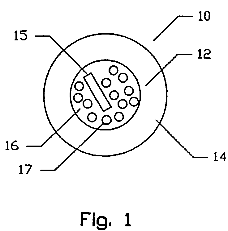
[0057]Turning to FIG. 1, the present invention is intended to be used in association with narrow gauge fibre optic cables 10, composed of a polycarbonate and polyester alloy outer casing 12 such as GE Plastics Enoy™ material and an inner core 16. The core is composed of multiple optical fibres 17 and a moisture-blocking element 15. The core is preferably wrapped with a moisture barrier 14. The moisture-blocking element 15 comprises a string with super absorbent polymer (SAP) embedded into its fibres extending the length of the cable. The outside diameter of the cable casing is about 3.8 mm (about 0.15 inches) with a wall thickness of about 0.9 mm. The fibre used is a non-ribbonized coloured loose fibre with a diameter of 0.25 mm. These dimensions are by way of example only and may be varied to suit the application as is known in this art.

[0058]The relatively narrow cable contemplated for use in this invention allows for easy placement into saw cuts made by common diamond blades. For...


PUM


Abstract

A method of installing fibre optic cables consists of cutting a shallow and narrow trench or channel within a road surface or building wall. A narrow fibre optic cable is laid within the channel, and subsequently covered with a patch material. A branching cable network is provided by cutting at periodic and selected locations, a slightly broader and deeper region of the channel, within which cable loops and / or junction boxes are installed. The nodes may consist of branching nodes, or alternatively non-branching nodes containing a cable loop and / or junction box, the installation of which at a location permits a junction node to be formed at a close by location. The invention also consists of a junction box for use with the system.

Description

[0001]This application is a continuation of U.S. application Ser. No. 10 / 071,419, filed on Feb. 7, 2002, now U.S. Pat. No. 6,807,355, which claims priority from Canadian Patent Application No. 2,337,284 to Dofher, entitled “Subsurface Fibre Optic Cable Network Installation” filed Feb. 15, 2001.FIELD OF THE INVENTION[0002]The present invention relates to subsurface installation of fibre optic cables, for example, in urban settings where cable is laid buried under the surfaces of streets or sidewalks. As well, the invention relates to fibre optic cable installation within masonry construction and other construction, as well as systems for forming a branching fibre optic cable network.BACKGROUND OF THE INVENTION[0003]With the rapidly growing need for high-speed data connections to businesses and residences (driven mainly by the need to access the Internet) a faster and more economical method is needed in order to deliver these connections. Optical fibre offers the greatest potential to...

Claims


Application Information

Patent Timeline
Patent Type & Authority Patents(United States)
IPC IPC(8): G02B6/44G02B6/00G02B6/50H02G1/06H02G9/02H04B10/25H04B10/27
CPCG02B6/4441G02B6/504G02B6/4451G02B6/501
Inventor DOFHER, DARREN
Owner TERASPAN NETWORKS
Why Eureka
Try Eureka