Laser oscillator, optical communication method and system

a laser resonator and optical communication technology, applied in the field of laser resonators and optical communication methods and systems, can solve the problems of large change in oscillating frequency, inability to demodulate data, and inability to guarantee the resonant frequency of laser resonators attempting synchronous oscillation. to achieve the effect of increasing the reliability of optical communication systems

Inactive Publication Date: 2006-05-23
NIPPON TELEGRAPH & TELEPHONE CORP
View PDF14 Cites 16 Cited by
  • Summary
  • Abstract
  • Description
  • Claims
  • Application Information

AI Technical Summary

Benefits of technology

[0012]The present invention has been realized in consideration of the above matters. It is an object of this invention to increase the reliability of an optical communication system by providing an extremely advanced technique for scrambling an optical signal based on quantum mechanical fluctuation, thereby invalidating illicit activities such as wire-tapping.
[0018]This invention uses quantum fluctuation to separate a signal light into two or more noises, which are difficult to reproduce by artificial methods. Consequently, when receiving only one wavelength, it is only possible to detect chaotic noise components. Therefore, data demodulation by tapping can be almost completely prevented. Furthermore, after one signal light has been separated into multiple wavelength components, these are transmitted along different paths, and consequently, the possibility of demodulating the data by tapping is also made completely physically impossible, whereby a communication services which are extremely reliable can be provided.

Problems solved by technology

According to this method, without the aforementioned special means for extracting the carrier component, a signal detected by a conventional communication method for directly detecting ordinary signal light would always be distorted, making it impossible to demodulate the data.
Consequently, a large amount of change in the oscillating frequency is caused by fluctuation of the laser resonator (e.g. thermal and mechanical fluctuation of the resonator length).
As a result, it is impossible to guarantee that the resonant frequency of the laser resonator attempting the synchronous oscillation will remain within the frequency bandwidth of the other laser resonator for a long period of time.
Furthermore, when the person performing the tapping has means for demodulating the signal obtained by synchronous oscillation as described above, conventional methods offer no physical means of stopping him from demodulating the tapped signal.

Method used


Image

  • Laser oscillator, optical communication method and system
  • Laser oscillator, optical communication method and system
  • Laser oscillator, optical communication method and system

Examples


embodiment 1

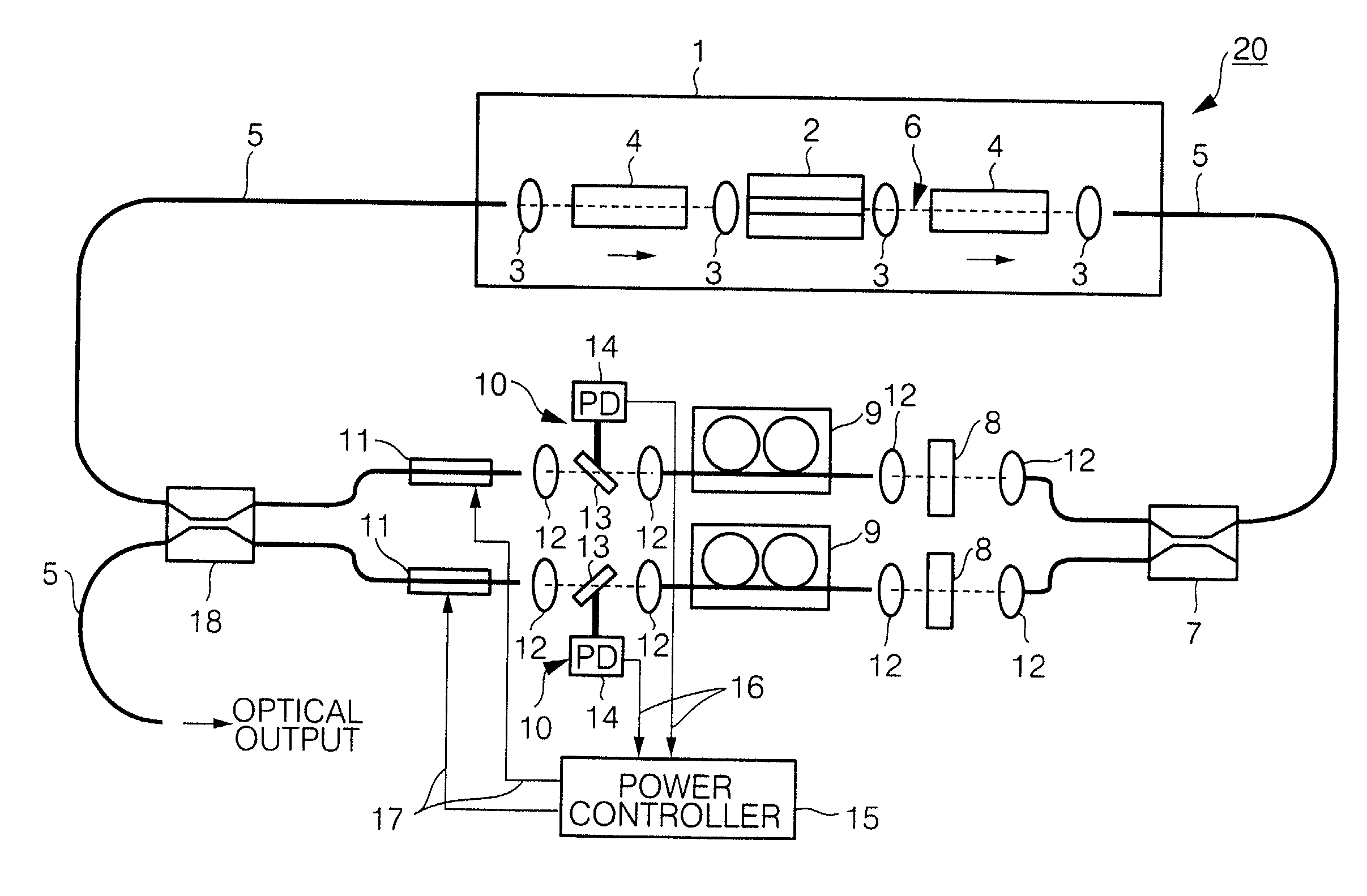
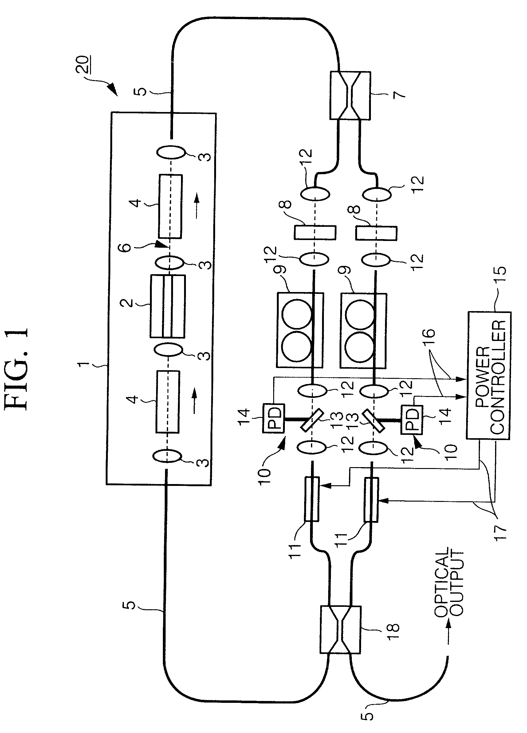
[0040]FIG. 1 shows the constitution of a laser oscillator according to a first embodiment of the present invention. As shown in FIG. 1, a semiconductor light amplifier 1 is provided as a light-amplifying medium which operates in a gain saturation state, and comprises isolators 4, which are connected to the input and output of a semiconductor light-amplifying element 2 (optical negative feedback element), comprising a semiconductor waveguide, with collimating lenses 3 therebetween, the lenses 3 forming a collimate beam 6, and two additional lenses 3 which couple the semiconductor light amplifier 1 to optical fibers 5.

[0041]The semiconductor light-amplifying element 2 amplifies light by stimulated emission in the same manner as a semiconductor laser, but has features for blocking end-face reflection, such as an anti-reflection coat and diagonal emission faces. A window structure having a band-gap is provided in order to reduce the rate of absorption near the emission faces, and preven...

embodiment 2

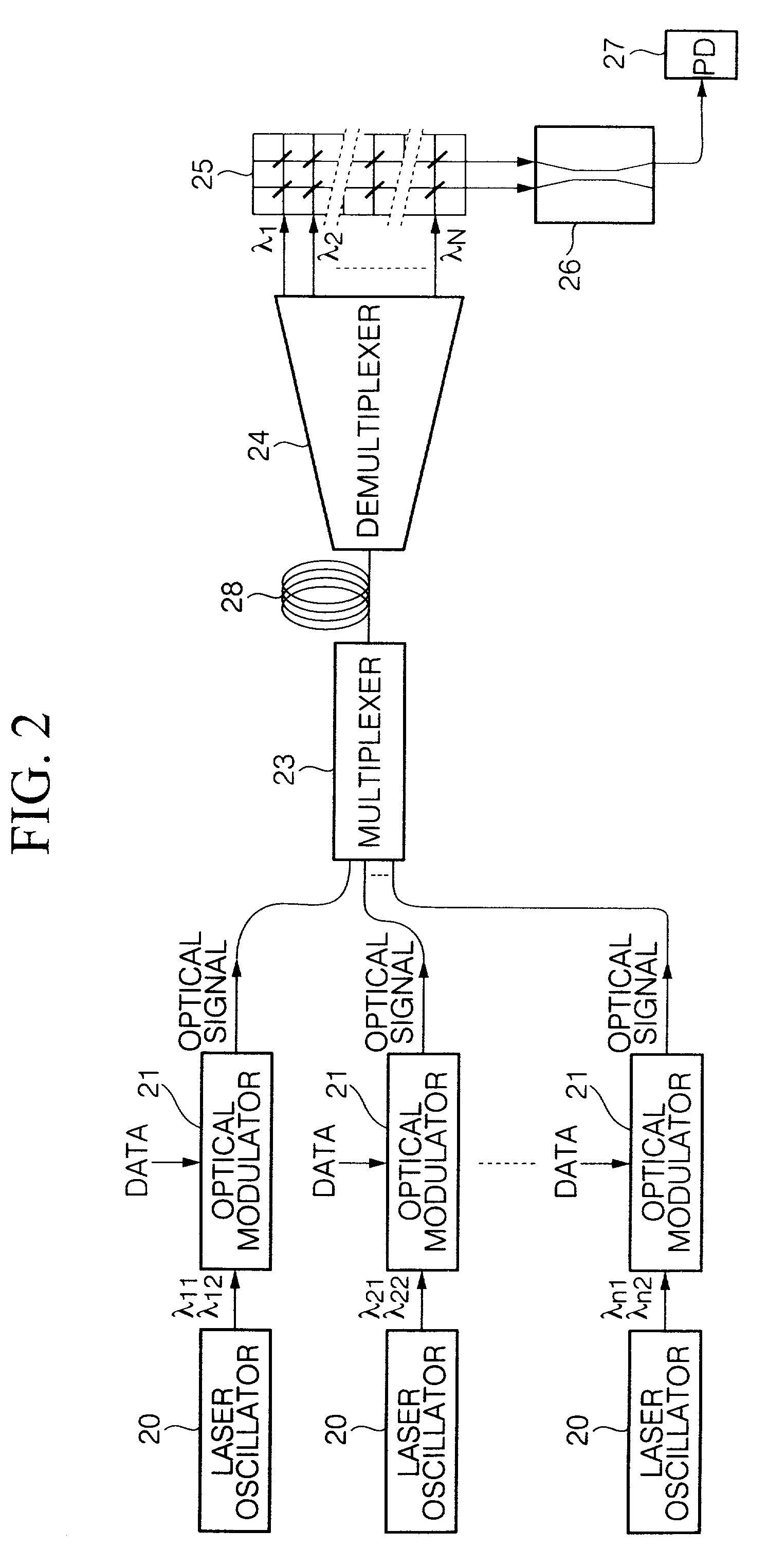
[0052]FIG. 2 is a block diagram showing an optical communication method according to a second embodiment of the present invention. As shown in FIG. 2, an optical communication system is provided with a transmitting section, a receiving section, and a transmission path 28 therebetween. The transmitting section comprises, for example, a plurality of laser oscillators 20 according to the first embodiment, which generate laser light (at two simultaneous wavelengths laser oscillation in this example) such as λ11, λ12 (i=1, 2, . . . n). The 2n wavelengths are set to different values. Optical modulators 21 create optical signals by encoding simultaneously at two wavelengths based on data to be transmitted, and a multiplexer 23 multiplexes the optical signals and transmits them in a single transmission via the transmission path 28.

[0053]In the receiving section, a demultiplexer 24 temporarily demultiplexes all the wavelength components. A wavelength multiplexer / demultiplexer using an array ...

embodiment 3

[0056]FIGS. 3 and 4 are diagrams showing an optical communication method according to a third embodiment of the present invention. FIG. 3 shows the constitution of a transmitting section, which is the same as the second embodiment in that it comprises a plurality of units for obtaining optical signals by using optical modulators 21 to encode data to be added to laser light from the laser oscillators 20, simultaneously oscillated at two wavelengths.

[0057]The multiplexer 23 multiplexes the optical signals, and the demultiplexer 24 demultiplexes them into their separate wavelength components λ1, λ2, . . . , λN. Thereafter, an N×N optical switch 31 rearranges the simultaneously oscillation wavelengths λ11, λ12 (i=1, 2, . . . , n) by dividing them into two wavelength groups λ11, λ21, . . . , λn1 and λ12, λ22, . . . , λ12. Moreover, two multiplexers 32 and 33 create wavelength-multiplexed signals by multiplexing each of the two wavelength groups, and transmit them along independent and eq...


PUM


Abstract

Extremely advanced technology for scrambling an optical signal based on quantum mechanical fluctuation is used to provide a highly reliable optical communication method which can invalidate illicit activities such as wire-tapping, a system, and a laser oscillator which is used in the method and system. A transmitter side generates laser light, simultaneously oscillated at a plurality of wavelengths, the total number of generated photons being constant, and transmits a signal light comprising data which has been added to the light of the plurality of wavelengths; and at a receiving side, light, simultaneously oscillated at the plurality of wavelengths, is selected from the signal light, and the data is demodulated.

Description

BACKGROUND OF THE INVENTION[0001]1. Field of the Invention[0002]The present invention relates to a laser oscillator and an optical communication method and system. The invention specifically relates to technology for scrambling optical signals, which can be used in a highly reliable optical communication system which invalidates illicit activities such as wire-tapping.[0003]2. Description of the Related Art[0004]In an optical communication system using optical fiber as a transmission medium, the communication can be tapped in the same manner as electrical communications using electrical wires by locally bending the optical fiber so that the mode of transmitting along the optical fiber is easily converted to an radiation mode, thereby enabling the light which is being transmitted in the optical fiber to be extracted to the outside. Furthermore, a communication system using spatial light propagation can easily be tapped by providing an optical receiver in the same manner as radio comm...

Claims


Application Information

Patent Timeline
Patent Type & Authority Patents(United States)
IPC IPC(8): H04B10/00H04B10/85H04K1/00H04L9/00
CPCH04B10/85H04L9/001H04K1/00H04L2209/08
Inventor KATAGIRI, YOSHITADAHASHIMOTO, ETSUSUZUKI, KENICHI
Owner NIPPON TELEGRAPH & TELEPHONE CORP
Why Eureka
Try Eureka