Highly integrated microwave outdoor unit (ODU)

a microwave outdoor unit, high-integration technology, applied in the direction of collapsable antenna means, quick-release antenna elements, particular array feeding systems, etc., can solve the problems of low operational reliability, high cost of fabricating and testing outdoor units, and high manual labor. , to achieve the effect of reducing the use of cables and wiring harnesses, rapid connection and disconnection

Inactive Publication Date: 2006-05-23
REVEAL IMAGING
View PDF26 Cites 64 Cited by
  • Summary
  • Abstract
  • Description
  • Claims
  • Application Information

AI Technical Summary

Benefits of technology

[0011]An intermediate frequency (IF) board is mounted in the housing and has components forming an intermediate frequency circuit operable with the millimeter wave transceiver circuit. A frequency synthesizer board is mounted within the housing. A controller board is mounted within the housing and has surface mounted DC and low frequency discrete devices thereon forming power and control circuits that supply respective power and control signals to other circuits on other boards. Circuit contact members interconnect the circuits between boards, wherein the use of cables and wiring harnesses is minimized. A quick connect / disconnect assembly is operative with the housing for allowing the housing to be rapidly connected and disconnected to the antenna.

Problems solved by technology

This method of fabricating and testing outdoor units is expensive, requires much manual labor, and results in low operational reliability.

Method used


Image

  • Highly integrated microwave outdoor unit (ODU)
  • Highly integrated microwave outdoor unit (ODU)
  • Highly integrated microwave outdoor unit (ODU)

Examples


Embodiment Construction

[0036]The present invention will now be described more fully hereinafter with reference to the accompanying drawings, in which preferred embodiments of the invention are shown. This invention may, however, be embodied in many different forms and should not be construed as limited to the embodiments set forth herein. Rather, these embodiments are provided so that this disclosure will be thorough and complete, and will fully convey the scope of the invention to those skilled in the art. Like numbers refer to like elements throughout.

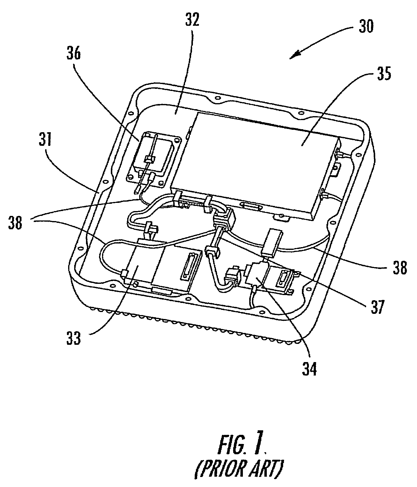
[0037]The present invention advantageously reduces the size and cost of a conventional, broadband outdoor unit used in high speed and high data rate wireless communications. The present invention is advantageous over digital subscriber line (DSL), cable modem, or similar communications systems, and can be used in point-to-point, point-to-multipoint, Local Multipoint Distribution Service (LMDS), and mesh communication architectures. The present invention re...


PUM


Abstract

A lightweight millimeter wave outdoor unit includes a lightweight housing with a heat sink and mounting member configured for mounting on the antenna to form a wireless link. A millimeter wave transceiver board is formed of ceramic material and mounted within the housing. It includes a millimeter wave transceiver circuit that has microwave monolithic integrated circuit (MMIC) chips and operable with the transmit and receive boards. An intermediate frequency (IF) board has components forming an intermediate frequency circuit operable with the millimeter wave transceiver circuit. A frequency synthesizer board has a signal generating circuit for generating local oscillator signals to the transceiver circuit. A controller board has surface mounted DC and low frequency discrete devices thereon forming power and control circuits that supply respective power and control signals to other circuits on other boards. A quick connect/disconnect assembly is operative with the housing for allowing the housing to be rapidly connected and disconnected to the antenna circuit contact members interconnect circuits between boards.

Description

FIELD OF THE INVENTION[0001]This invention relates to the field of wireless outdoor units, and more particularly, this invention relates to the field of millimeter wave, wireless terrestrial outdoor units that use microwave monolithic integrated circuits (MMIC).BACKGROUND OF THE INVENTION[0002]The increased demand for high-speed, high data rate communications has created an immediate need for broadband access to the related network infrastructure. New applications include computer-to-computer communications, gaming, and video-based services. Wireless solutions offer benefits in ease of deployment without the requirement of destroying streets to lay fiber. Wireless solutions also offer increased flexibility because new communication links can be added to the network as customers are added. Wireless solutions are also less expensive compared to optical fiber and hardwired solutions.[0003]The use of millimeter wave (MMW) frequency bands allows wireless links to produce up to about an e...

Claims


Application Information

Patent Timeline
Patent Type & Authority Patents(United States)
IPC IPC(8): H04B1/38H01Q1/02H01Q1/08H01Q1/42H01Q21/00
CPCH01Q1/02H01Q1/088H01Q21/0087H01Q21/0025H01Q1/42H01Q21/00H04B1/50H04B7/15
Inventor AMMAR, DANNY F.BASS, DAVIDCLARK, GAVINGRAHAM, RONALD D.JORDAN, CONRADSTAHLY, STEPHEN A.
Owner REVEAL IMAGING
Why Eureka
Try Eureka