Automatic generation of programmable logic device architectures

Inactive Publication Date: 2006-05-23
INTEL CORP
View PDF11 Cites 48 Cited by
  • Summary
  • Abstract
  • Description
  • Claims
  • Application Information

AI Technical Summary

Benefits of technology

[0034]FIG. 8(b) is a simplified block diagram showing a good connection block pattern;
[0035]FIG. 9(a) is a simplified diagram showing a disjoint switch block;
[0036]FIG. 9(b) is a simplified diagram showing a segmentation distribution;
[0037]FIG. 10 is a simplified block diagram of conflicting horizontal and vertical constraints

Problems solved by technology

This is an enormous amount of data—typically tens to hundreds of megabytes (MB) in size.
Accordingly, it is not practical for a PLD architect to specify this data directly for every PLD architecture in which he or she is interested.
However, it is not very practical to specify this routing-resource graph manually because the routing-resource graph for a typical PLD requires an enormous amount of data—typically in the tens to hundreds of MBs of memory in size.
Essentially, this is too low-level a description for a PLD architect to use conveniently.
However, even the manual

Method used


Image

  • Automatic generation of programmable logic device architectures
  • Automatic generation of programmable logic device architectures
  • Automatic generation of programmable logic device architectures

Examples


Embodiment Construction

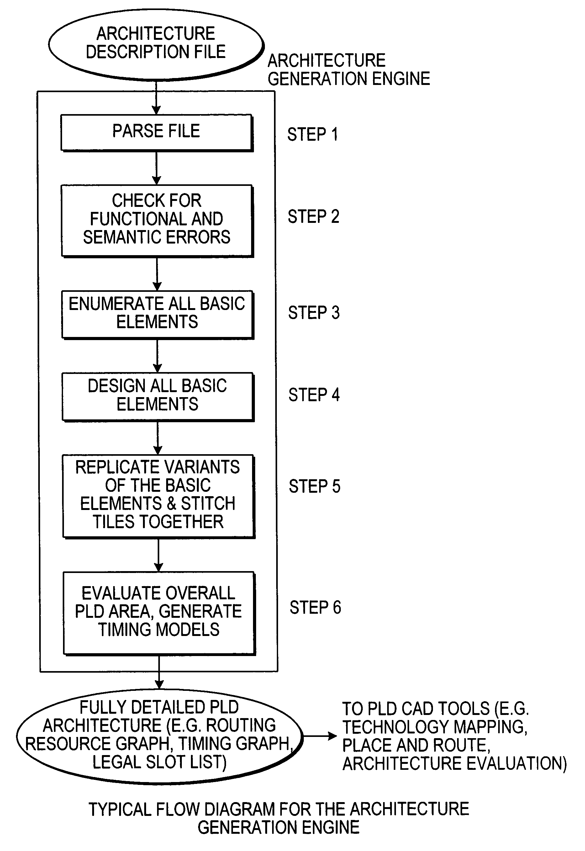
[0040]The architecture generation engine of the invention converts a preferably concise high-level description of a PLD architecture into a fully detailed is description required by CAD tools to implement circuits in a PLD and to estimate the performance of the architecture. A preferred implementation of how to represent a PLD architecture concisely, and to automatically generate the fully detailed representation of the architecture is described below. Many variations of this preferred implementation are possible, however, including using only a subset of the parameters listed below to describe a PLD or using a different set of parameters.

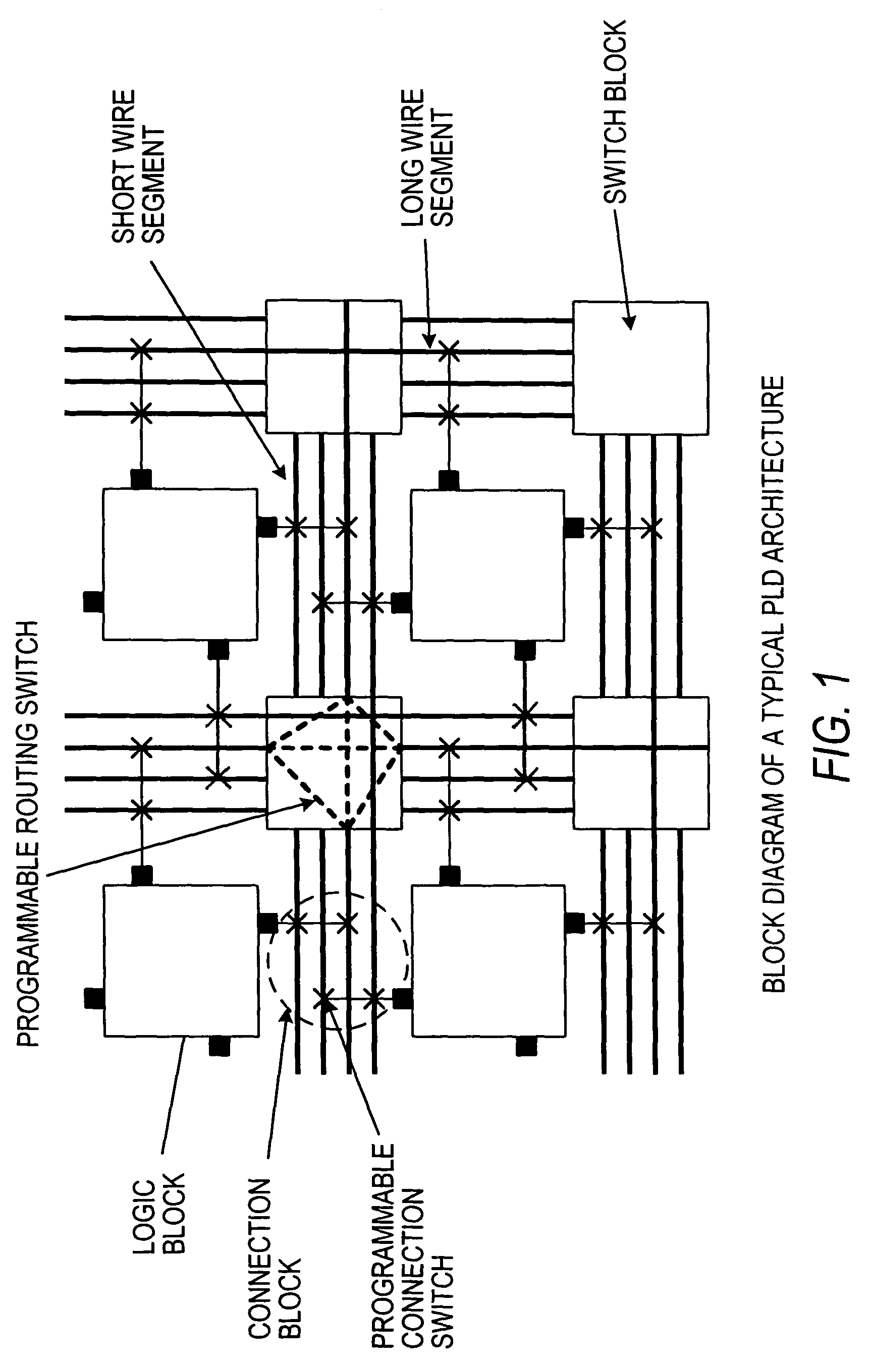
[0041]With a high-level PLD architecture description language, the PLD designer describes the architecture using:[0042]The various “types” of wire used in the PLD, including the wire length (number of logic blocks spanned), and the wire resistance and capacitance, or other delay metric;[0043]The various “types” of programmable routing switch used i...


PUM


Abstract

An “architecture generation engine” is operative with a CAD system to implement circuits into PLD (programmable logic device) architectures and to evaluate performances of different architectures. The architecture generation engine converts a high level, easily specified description of a PLD architecture into a highly detailed, complete PLD architecture database that can be used by a CAD toolset to map a circuit netlist into a PLD. The architecture generation engine also enables performance evaluation of a wide variety of PLD architectures for given benchmark circuits.

Description

CROSS REFERENCE TO RELATED APPLICATION[0001]This is a continuation of U.S. patent application Ser. No. 09 / 429,013, filed Oct. 29, 1999, now U.S. Pat. No. 6,631,510, which is incorporated by reference herein in its entirety.BACKGROUND OF THE INVENTION[0002]This invention relates generally to programmable logic devices (PLDs), and more particularly to a method and system for generation and evaluation of architectures for such devices.[0003]PLDs are a widely used form of integrated circuit because of the flexibility provided by their customizable nature. In general, PLDs include field programmable gate arrays (FPGAs), complex programmable logic devices (CPLDs), simple programmable logic devices, and laser programmable devices. Architecturally, a PLD includes logic blocks and input / output (I / O) blocks which are connectable through a programmable interconnect structure.[0004]A typical PLD is an integrated circuit chip that, wholly or in part, includes an array of one or more logic blocks...

Claims


Application Information

Patent Timeline
IPC IPC(8): G06F17/50
CPCG06F17/5054G06F30/34
Inventor BETZ, VAUGHNROSE, JONATHAN
Owner INTEL CORP
Why Eureka
Try Eureka