

Method of fabricating a rotor
- Summary
- Abstract
- Description
- Claims
- Application Information
AI Technical Summary
Benefits of technology
Problems solved by technology
Method used
Image

Examples
Embodiment Construction
[0013]U.S. Ser. No. 09 / 952,319, assigned to assignee of this invention, includes a detailed description of multi-layer motor geometry and is hereby incorporated by reference in its entirety.
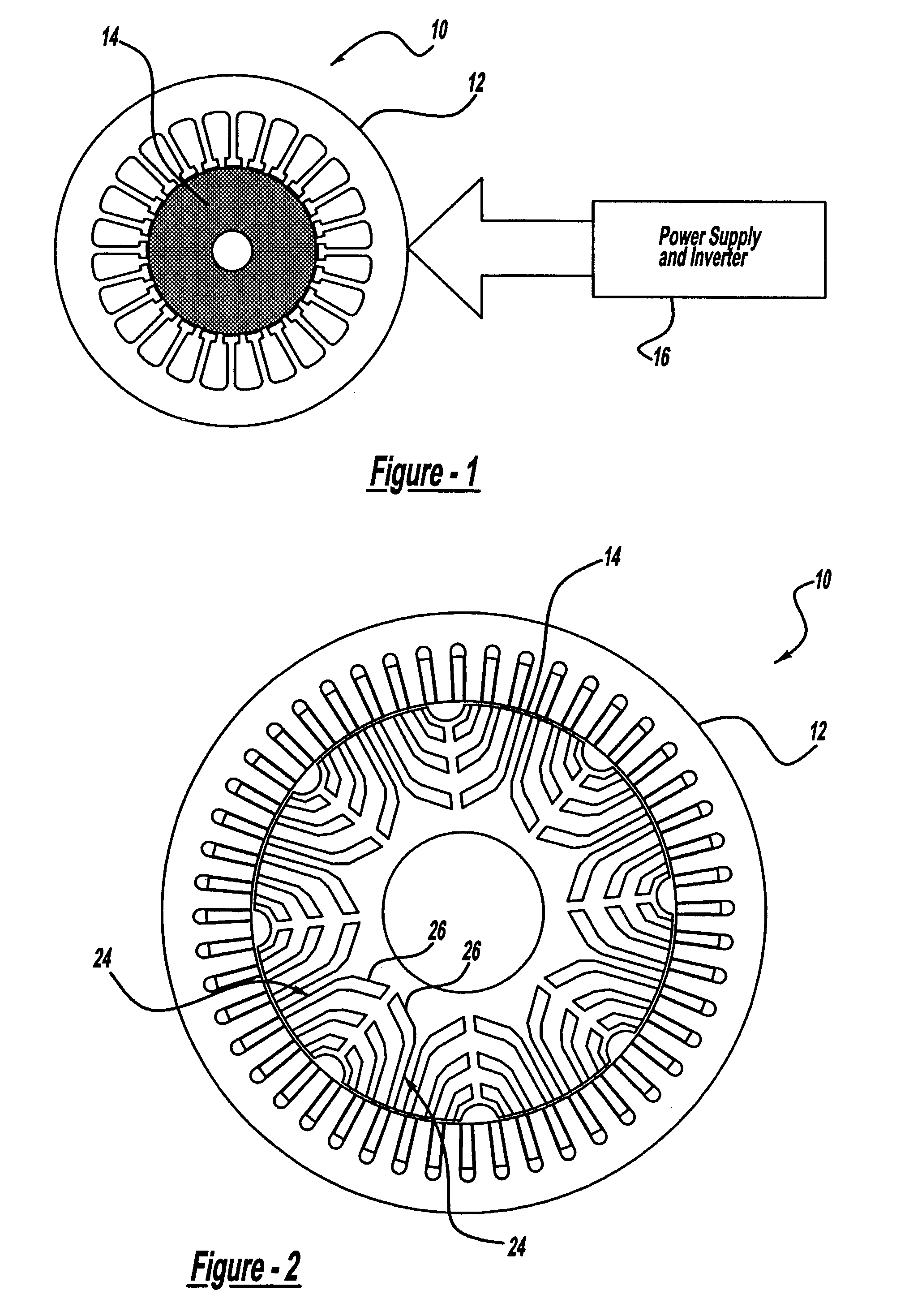
[0014]FIG. 1 is a diagrammatic drawing of a permanent magnet motor 10 having a wound stator12 and permanent magnet rotor 14. A power supply and inverter 16 commutate and control the speed and torque of the motor 10 in response to feedback including, but not limited to, an encoder, resolver, tachometer, proximity switch and tooth set, and back electromotive force (emf) detection. The motor may be characterized as a brushless DC motor with square wave or sinewave excitation provided by the power supply and inverter 16.
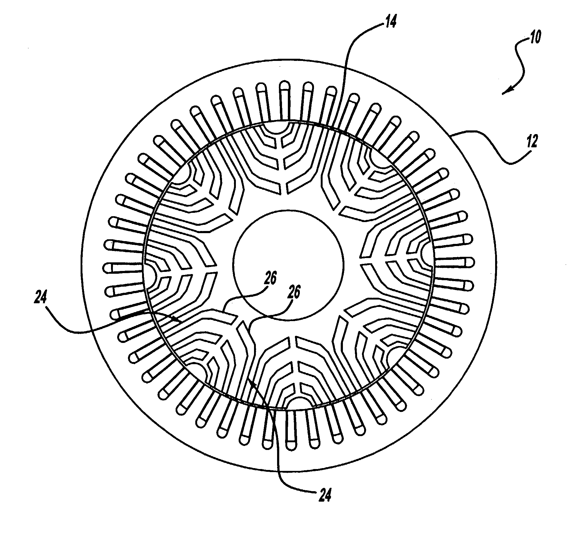
[0015]FIG. 2 is a cross section of a multi-layer or barrier buried magnet rotor geometry. Regions 26 of the magnetic material layers or barriers 24 will be difficult to fully magnetize because of the distance from the rotor 14 surface. The magnetic material layers 24 surface may be ma...
PUM
| Property | Measurement | Unit |
|---|---|---|
| Energy | aaaaa | aaaaa |
Abstract
Description
Claims
Application Information