Piezoelectric quartz plate and method of cutting same

a technology of quartz plate and piezoelectric technology, which is applied in the field of piezoelectric quartz plate and cutting method, can solve the problems of increasing the need for smaller piezoelectric devices, increasing the cost of manufacturing, and increasing the cost of providing corrections for errors, so as to facilitate manufacturability, reduce frequency deviation, and increase the accuracy of curve fit.

Inactive Publication Date: 2006-05-30
BRANHAM MARK
View PDF27 Cites 6 Cited by
  • Summary
  • Abstract
  • Description
  • Claims
  • Application Information

AI Technical Summary

Benefits of technology

[0064]Further refinements would increase the accuracy of the fit of the curve to the known cuts, but as a first order approximation, the addition of the basic velocity proportional damping term accounts for much more of the known quartz behavior than does the prior mathematical description alone.
[0065]To test the model, a trial cut was made in the area close to the GT cut angle of 51°. The concept being that an ideal commercial cut would have a lower third order coefficient similar to the GT cut, but unlike a plate made using a GT cut where the edges of the blank are vibrating and the center is not vibrating, an ideal commercial cut would vibrate in a shear like mode such that the edges of the quartz plate do not vibrate like the familiar AT cut. This would facilitate manufacturability, a key obstacle to the adoption of the GT cut despite its technical advantage of a low frequency deviation over an exceptionally wide temperature range. Test cuts in the range of interest produced the results illustrated in FIG. 8.
[0066]This experiment shows that reduced frequency deviation can be obtained over a wide temperature range as compared to the industry standard AT cut. This reduction in frequency deviation allows the quartz plate to perform temperature compensation functions that are currently required in modern designs. The elimination of these compensation electronics reduces both electronics cost and complexity. Conversely, applying the compensation electronics to the new crystal cut would achieve tighter frequency control in a given application.

Problems solved by technology

The internal constraints of communication devices also demand small frequency deviation as a function of temperature, and as consumer demand continually drives down the size and the cost of this equipment, the need for smaller piezoelectric devices that can maintain tight temperature performance and that are less costly to manufacture becomes increasingly greater.
In mass production a low margin of error results in substantial increases in manufacturing costs and in the additional cost of providing corrections for errors made.
It suffers, though, from the fact that, to get a reasonably high frequency from this type of length vibrating cut, too small a length to be practical is required.
The AT cut, although widely used, does not perform well when mechanically and thermally stressed.
This requirement has resulted in the use of external temperature compensation schemes being applied to systems utilizing AT-cut quartz resonators, which increases cost, time, and system complexity.
There are other angles of cut, but they all suffer from either strong frequency dependence on temperature or on the presence of competing modes of vibrations.

Method used


Image

  • Piezoelectric quartz plate and method of cutting same
  • Piezoelectric quartz plate and method of cutting same
  • Piezoelectric quartz plate and method of cutting same

Examples


Embodiment Construction

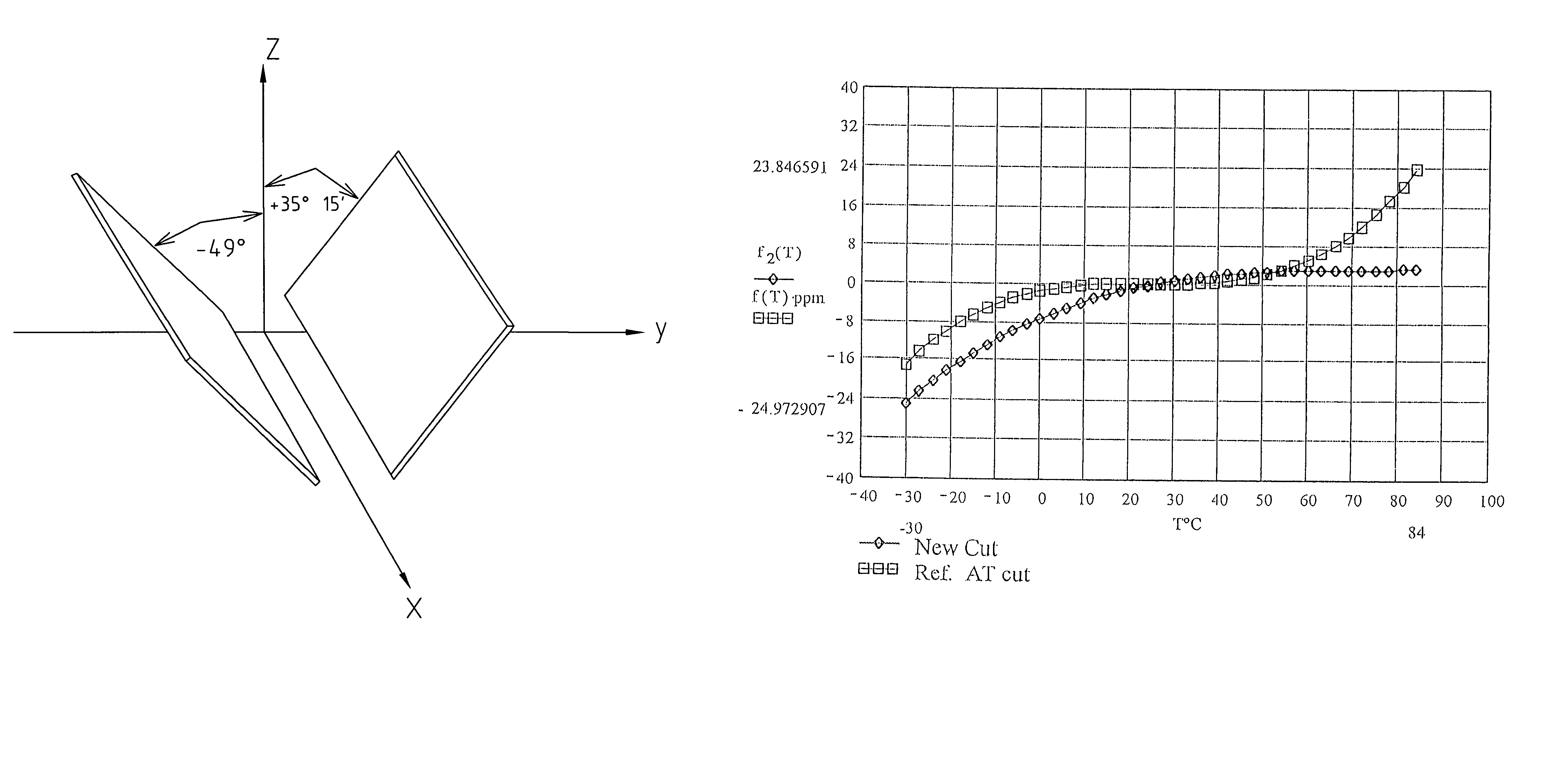
[0043]This invention relates to, and claims, quartz crystals (as articles of manufacture) cut at specific calculated angles to the method that is used to select specific angles of cut to obtain quartz plates having desired properties. Control devices in radios, cellular telephony, and other modem communications devices demand that shifts in frequency caused by temperature fluctuations be kept to a minimum. One advantage of the new cut angles of the present invention stems from the fact that quartz crystals manufactured according to the present invention exhibit low shifts in natural frequency of resonance as a function of changes in temperature. This invention also describes and claims a method that allows the manufacture of quartz plates that counteract frequency shifts over temperature excursion caused by other electrical components that make up typical oscillator circuits. In addition, this invention enables and claims angles of cut selected for a desired margin of error, which p...


PUM

PropertyMeasurementUnit
angleaaaaaaaaaa
angleaaaaaaaaaa
angleaaaaaaaaaa

Abstract

A piezoelectric quartz plate having reduced frequency deviation as a function of temperature, wherein the quartz plate is cut at an angle described by:
Tf=3.9+6.5cos2θ+12[c66Tc66sin2θ+c44Tc44cos2θ+Tc14c14sin2θc66sin2θ+c44cos2θ+c14sin2θ]+[a·(sin(ω·θ+ϕ)+sin(ω·θ+ϕ)2)]+δ
where quartz plate thickness is chosen in accordance with a desired frequency. This useful behavior can be manipulated such that a quartz plate is designed to counteract frequency shifts over temperature excursion of other electrical components found in typical oscillator circuits. The choice of angles of cut having larger margins of error means that quartz oscillators can be more easily reproduced on a large scale and at a lower cost than has traditionally been the case.

Description

CROSS REFERENCE TO RELATED APPLICATIONS[0001]This application is a Divisional of U.S. patent application Ser. No. 10 / 201,521, filed Jul. 23, 2002 now U.S. Pat. No. 6,744,182, which is a Continuation-in-Part of U.S. patent application Ser. No. 09 / 866,262, filed May 25, 2001 now abandoned.FIELD OF THE INVENTION[0002]The present invention relates to the field of quartz plate oscillators, and, more specifically, to a method for determining angles of cuts that produce quartz plates having low shifts in frequency as a function of temperature, and the manipulation of that method to reduce the effects of other electrical components.BACKGROUND OF THE INVENTION[0003]In 1980 the Curie brothers observed that when a permanently polarized material is subjected to a mechanical force an electric field is produced. Today, this phenomenon is referred to as the piezoelectric effect. Conversely, when an alternating electric current is applied to opposite faces of a piezoelectric crystal, the crystal ex...

Claims


Application Information

Patent Timeline
Patent Type & Authority Patents(United States)
IPC IPC(8): B28D1/04H03H9/02
CPCH03H9/02551Y10T29/42
Inventor BRANHAM, MARK
Owner BRANHAM MARK
Why Eureka
Try Eureka