Cable with shielding strip

a shielding strip and cable technology, applied in the direction of insulated conductors, power cables, cables, etc., can solve the problems of increasing pressure, affecting the service life of the cable, so as to reduce the effect of increasing pressure and reducing pressur

Inactive Publication Date: 2006-05-30
NKT CABLES GRP
View PDF7 Cites 17 Cited by
  • Summary
  • Abstract
  • Description
  • Claims
  • Application Information

AI Technical Summary

Benefits of technology

[0008]When using cable that requires shield for personal protection and for protection against short-circuits, the shield is normally constructed from copper wires, or a shield of copper wires is used, possibly also having aluminium foil applied to its outside. A galvanic element may arise when copper and aluminium come into contact with each other. Solutions are thus available for cables having copper shield and aluminium foil that minimise this effect. Despite this, major problems with corrosion often arise when the jacket is punctured, and these problems frequently lead to increased pressure and thus degradation of the outer conducting layer and the underlying insulation. The consequence of this is the risk of a complete break-down of the cable and subsequent interruption in electrical supply.

Problems solved by technology

Despite this, major problems with corrosion often arise when the jacket is punctured, and these problems frequently lead to increased pressure and thus degradation of the outer conducting layer and the underlying insulation.
The consequence of this is the risk of a complete break-down of the cable and subsequent interruption in electrical supply.
Another problem that may arise is that poor contact between different shield materials may give rise to differences in potential between these materials in the event of excess voltage transients, and this may degrade the outer conducting layer and the underlying insulation, or it may puncture the jacket, leading to the risk of subsequent cable break-down and interruption in electrical supply.
This galvanic corrosion is currently a problem for existing cable designs, in particular in the event of a hole arising in the foil and water penetration occurring.
Even if the underlying construction is longitudinally sealed for water, the galvanic corrosion can give rise to a local break in the shield of the cable.

Method used


Image

  • Cable with shielding strip
  • Cable with shielding strip
  • Cable with shielding strip

Examples


Embodiment Construction

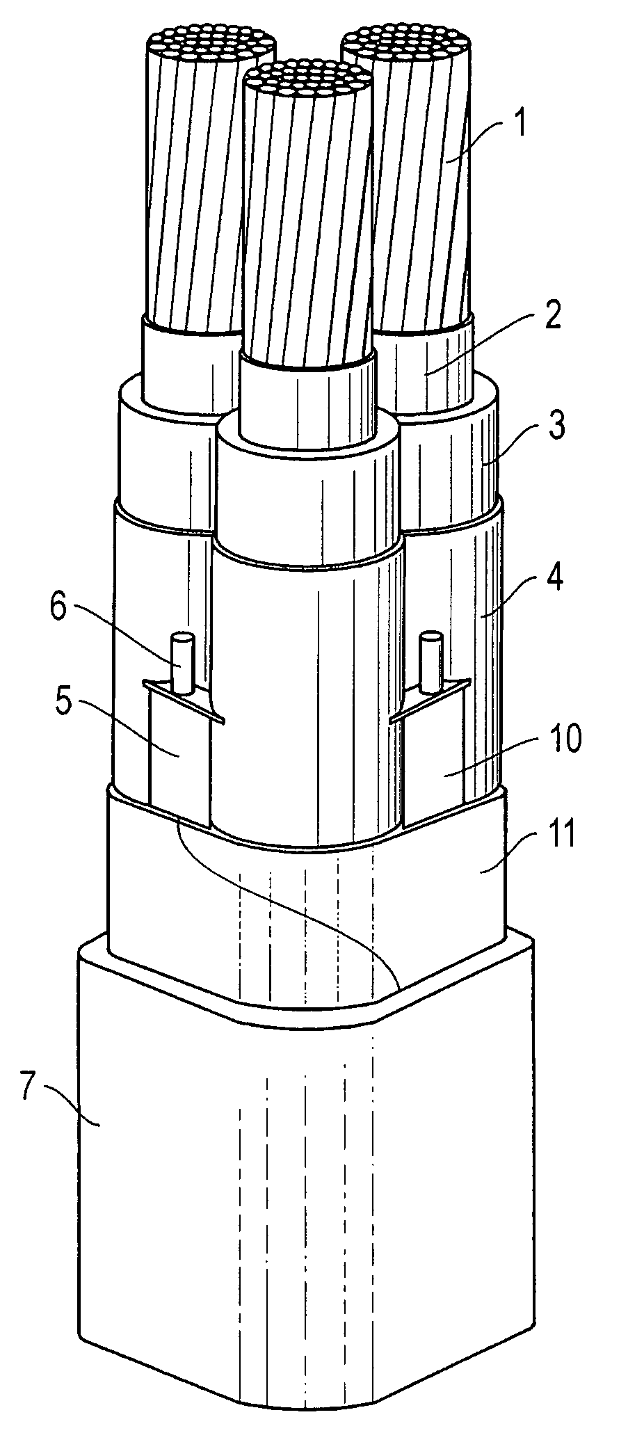
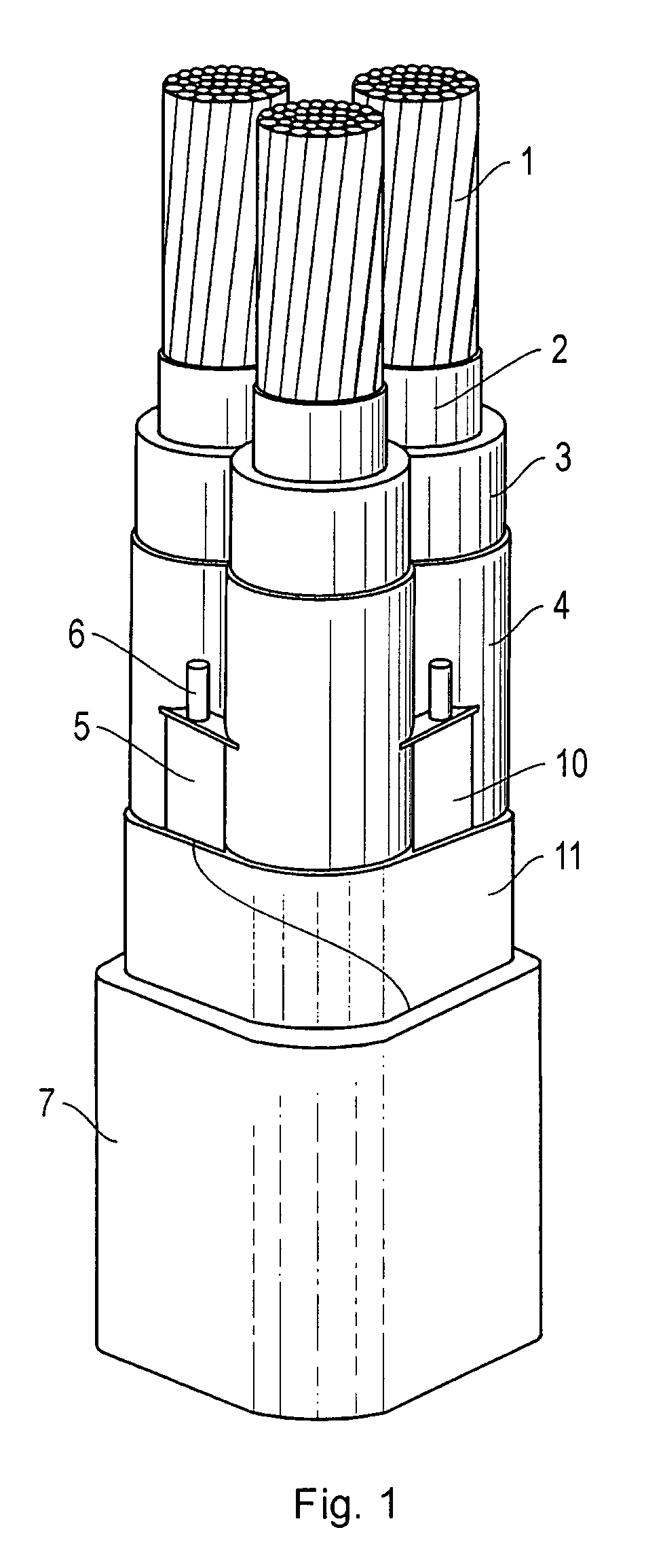
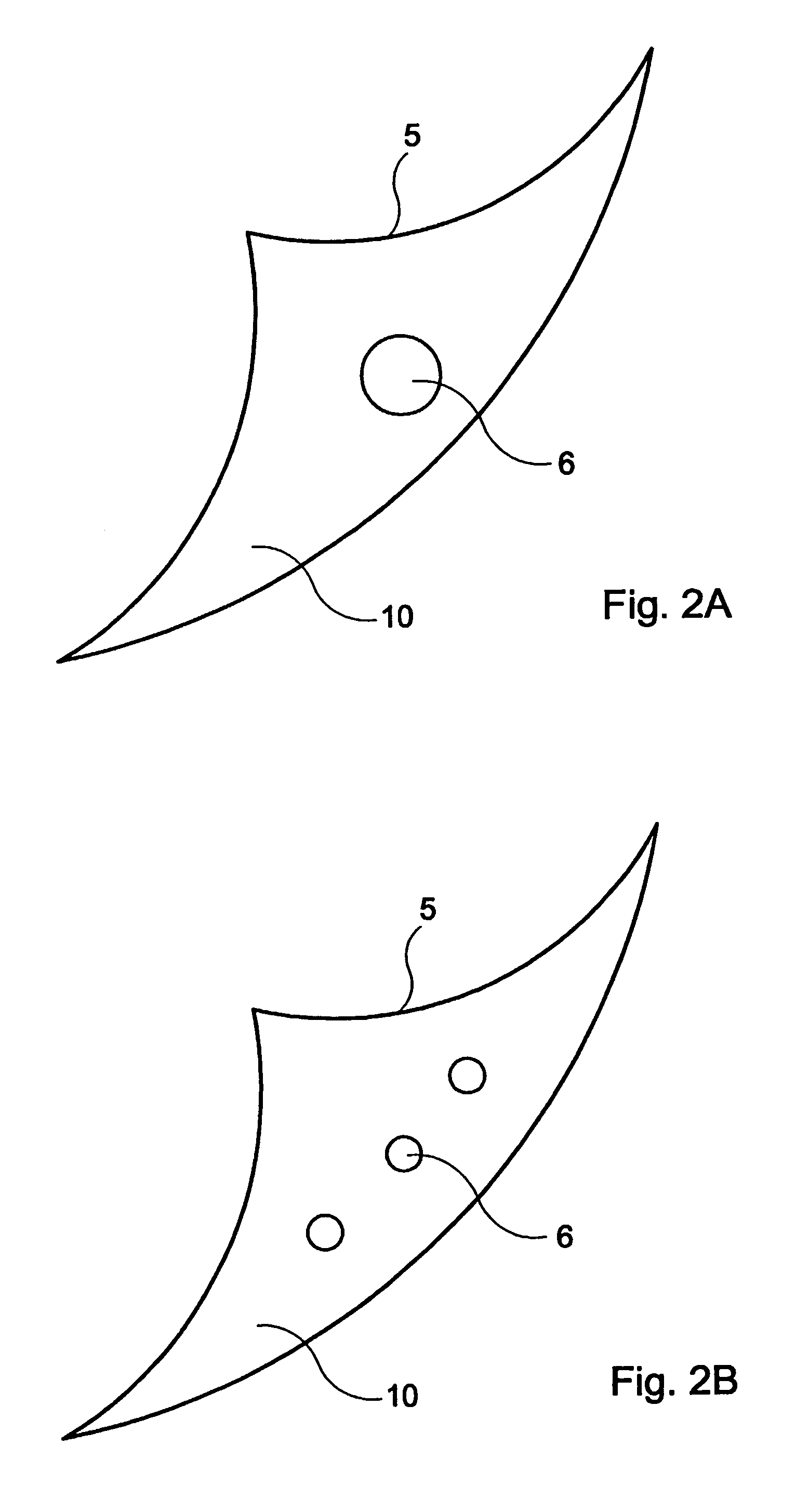
[0024]In FIG. 1 is shown by radial cross-sections an insulated electrical cable designed according to the invention. The cable consists of three insulated conductors 1, where an inner conducting layer 2, insulation 3 and an outer conducting layer 4 are arranged around each conductor. Several sectorial shield strips 5 with one or several longitudinal shield wires 6 baked into them are present in the space between the outer conducting layer and an outer foil 11 of metal such as aluminium, which strips are arranged to function as a metallic shield. These aluminium wires lie preferably baked into a filler material that protects against corrosion 10, known as shield wire filler material 10, which may be fully or partially conductive and may demonstrate swelling properties when in contact with water, whereby the tape or tapes preferably follow the cabling of the parts. Further, outside of the shield strips and in contact with them, a tape has been arranged that may consist of an aluminium...


PUM

PropertyMeasurementUnit
voltagesaaaaaaaaaa
humidityaaaaaaaaaa
voltagesaaaaaaaaaa

Abstract

The figure shows an electrical cable with conductors (1) of metal, surrounded by each of an inner conducting layer (2), insulation (3) and an outer conducting layer (4). A moisture barrier (11) with an electrically conducting layer surrounds the conductors. Shield strips (5) of at least partially conducting material are located in the regions between the outer conducting layer (4) and the moisture barrier (11). Electrically conducting shield wires (6) run along the shield strips and are placed through these into electrical contact with the electrically conducting layer of the moisture barrier (11). The shield strips support the moisture barrier from the inside, such that the moisture barrier can in a simple manner be made watertight when it is applied. The shield strips (5), the moisture barrier (11) and the shield wires (6) together constitute an efficient electrical shield for the cable. Penetration of an electrically conducting object into the cable results in a fault current that can be easily indicated, such that an applied cable voltage can be removed.

Description

TECHNICAL FIELD OF THE INVENTION[0001]The present invention concerns an insulated electrical cable with a shield of metallic foil for making it watertight in the radial direction and a jacket arranged outside of the shield.DESCRIPTION OF RELATED ART[0002]Insulated electrical cables for high voltages (>3 kV) are normally constructed in such a manner that that they consist of, from the centre, at least one conductor, at least one inner conducting layer, insulation, at least one outer conducting layer, a shield, and, externally, a jacket. The said type of cable is normally manufactured by what is known as “triple extrusion”, in which all three inner layers are extruded onto the conductor in a single process. The shield and the jacket are subsequently applied in a subsequent step. The most common insulation material is cross-linked polyethene (PEX).[0003]The role of the shield is both to ensure that the outer conducting layer is maintained at electrical earth potential by conducting ...

Claims


Application Information

Patent Timeline
Patent Type & Authority Patents(United States)
IPC IPC(8): H01B11/02H01B7/17H01B7/282H01B7/288H01B7/38H01B9/00H01B9/02
CPCH01B7/288H01B7/385H01B9/028H01B9/027H01B9/005
Inventor EFRAIMSSON, LARSJOHNSEN, ULFGATU, ANDERS
Owner NKT CABLES GRP
Why Eureka
Try Eureka