Reference device for evaluating the performance of a confocal laser scanning microscope, and a method and system for performing that evaluation

a reference device and laser scanning microscope technology, applied in the direction of optical radiation measurement, luminescent dosimeters, fluorescence/phosphorescence, etc., can solve the problems of no reference fluorescing target objects for characterizing key performances of confocal laser scanning microscopes, and quantitative fluorescence measurements that are erroneous and other problems

Inactive Publication Date: 2006-05-30
ROCHE MOLECULAR SYST INC
View PDF20 Cites 3 Cited by
  • Summary
  • Abstract
  • Description
  • Claims
  • Application Information

AI Technical Summary

Benefits of technology

[0016]The aim of the invention is therefore to provide a reference device, a method and a system of the above mentioned kinds that make it possible to evaluate quantitatively the performance of a confocal laser scan microscope for performing two-dimensional, quantitative fluorescence measurements.

Problems solved by technology

FIGS. 3a, 3b and 3c and this in turn leads to erroneous quantitative fluorescence measurements.
However, no reference fluorescing target objects for characterizing key performances of a confocal laser scan microscope, i.e., sensitivity, limit of detection, uniformity-, spatial resolution- and signal dynamic behavior over the scan field of view, have been reported yet.

Method used


Image

  • Reference device for evaluating the performance of a confocal laser scanning microscope, and a method and system for performing that evaluation
  • Reference device for evaluating the performance of a confocal laser scanning microscope, and a method and system for performing that evaluation
  • Reference device for evaluating the performance of a confocal laser scanning microscope, and a method and system for performing that evaluation

Examples


first embodiment

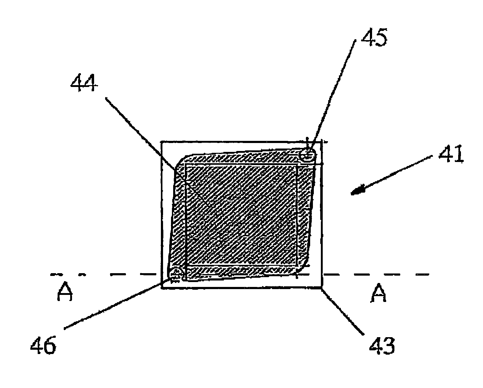
[0041]FIG. 5a shows a top view and FIG. 5b a cross-section of a reference device 41 according to the invention for characterizing quantitatively the homogeneity and sensitivity of a confocal laser scan microscope for two-dimensional quantitative fluorescence measurement.

[0042]The reference device 41 shown by FIGS. 5a and 5b consists of a top glass plate 42 bonded onto a glass substrate 43. The 16×16 square millimeter glass substrate 43 (thickness=1 millimeter) has a 5 micrometer etched planar cavity 44 (hatched area) which covers a surface of 11×11 square millimeters. The glass top plate 42 (thickness=0.7 millimeter) has two drilled holes 45 respectively 46 for fluid in- and outlet. Holes 45, 46 have each a diameter of 1.5 millimeter. The center of each hole 44, 45 lies at a distance of 1.38 millimeter from the edge of plate 42. In another possible embodiment, a top glass plate 42 without drilled holes 45 and 46 may not be bonded onto a glass substrate 43.

[0043]Glass substrate 43 ha...

second embodiment

[0051]FIG. 7a shows a top view and FIG. 7b a cross-section of a reference device according to the invention for a quantitative evaluation of the homogeneity and spatial resolution of a confocal laser scan microscope. FIG. 7c represents an enlarged view of FIG. 7a corner zone 55. FIG. 7d represents an enlarged view oft portion of FIG. 7a fluorescent zone 61 or 62.

[0052]In FIG. 7a some dimensions in micrometer are indicated. In FIG. 7b some dimensions in millimeters are indicated.

[0053]The reference device 51 shown by FIGS. 7a and 7b consists of a top glass plate 52 (thickness =0.7 millimeter) on a glass substrate 53 having an area of 16×16 square millimeter. The upper surface of glass substrate 53 (thickness 1 millimeter) has a 5 micrometer etched, microstructured depression forming a cavity 54 having a bottom inner surface. Cavity 54 is filled with uniformly dissolved fluorophores having a predetermined concentration, which leads to a predetermined spatial distribution of fluorescen...


PUM

PropertyMeasurementUnit
sizeaaaaaaaaaa
sizesaaaaaaaaaa
thicknessaaaaaaaaaa

Abstract

A reference device for evaluating the performance of a confocal laser scan microscope. The reference device comprises a substrate (53) and reference fluorescing matter distributed over a surface of the substrate (53). The reference fluorescing matter has a predetermined spatial distribution over the latter surface.

Description

[0001]This application is a US national phase application under 35 U.S.C. 371 of international patent application PCT EP01 / 06365, filed Jun. 5, 2001.FIELD OF THE INVENTION[0002]The invention concerns a reference device for evaluating the performance of a confocal laser scan microscope of the kind used for performing a two dimensional quantitative fluorescence measurement of test matter distributed on a flat surface of a first glass substrate in particular a DNA binding array or the like, e.g. a DNA binding array of the type described in U.S. Pat. No. 5,143,854.[0003]The invention also concerns a method for evaluating the performance of a confocal laser scan microscope of the above mentioned kind.[0004]The invention more in particular concerns an evaluation method enabling the characterization of a confocal laser scan microscope of the above mentioned kind in terms of quantitative signal detection sensitivity, limit of detection, uniformity of the confocal volume over the scan field ...

Claims


Application Information

Patent Timeline
Patent Type & Authority Patents(United States)
IPC IPC(8): G01N21/64G01N21/27G02B21/00G02B21/16
CPCG01N21/278G02B21/0076G02B21/0024
Inventor SCHMID, KARL ANTON JOSEFSCHNELL, URBAN GEORG
Owner ROCHE MOLECULAR SYST INC
Why Eureka
Try Eureka