Rotor for dynamo-electric machine
a dynamo-electric machine and rotor technology, applied in the direction of magnetic circuit rotating parts, magnetic circuit shape/form/construction, windings, etc., can solve the problems of damage to the electrically-insulating coating of the wire material, insulation failure, and no consideration, so as to suppress the occurrence of winding disturbances
- Summary
- Abstract
- Description
- Claims
- Application Information
AI Technical Summary
Benefits of technology
Problems solved by technology
Method used
Image
Examples
embodiment 1
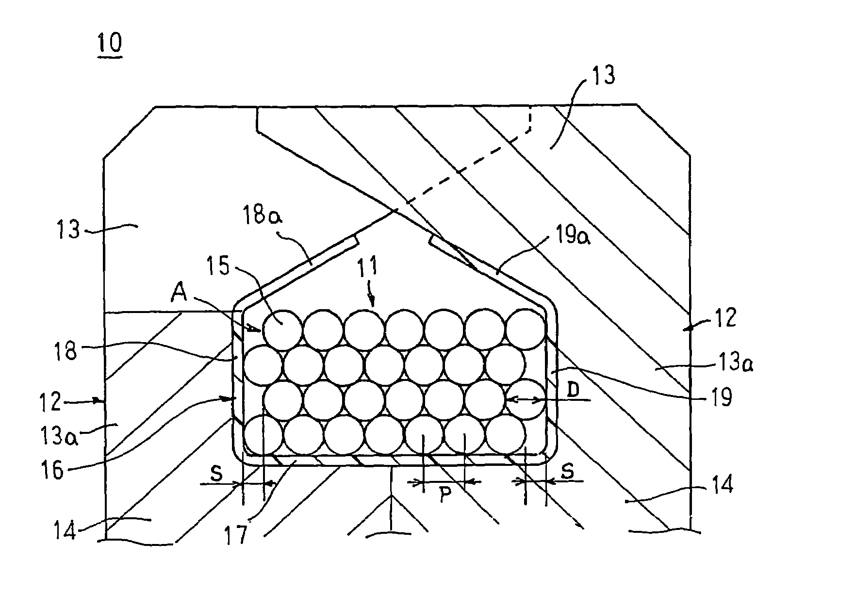
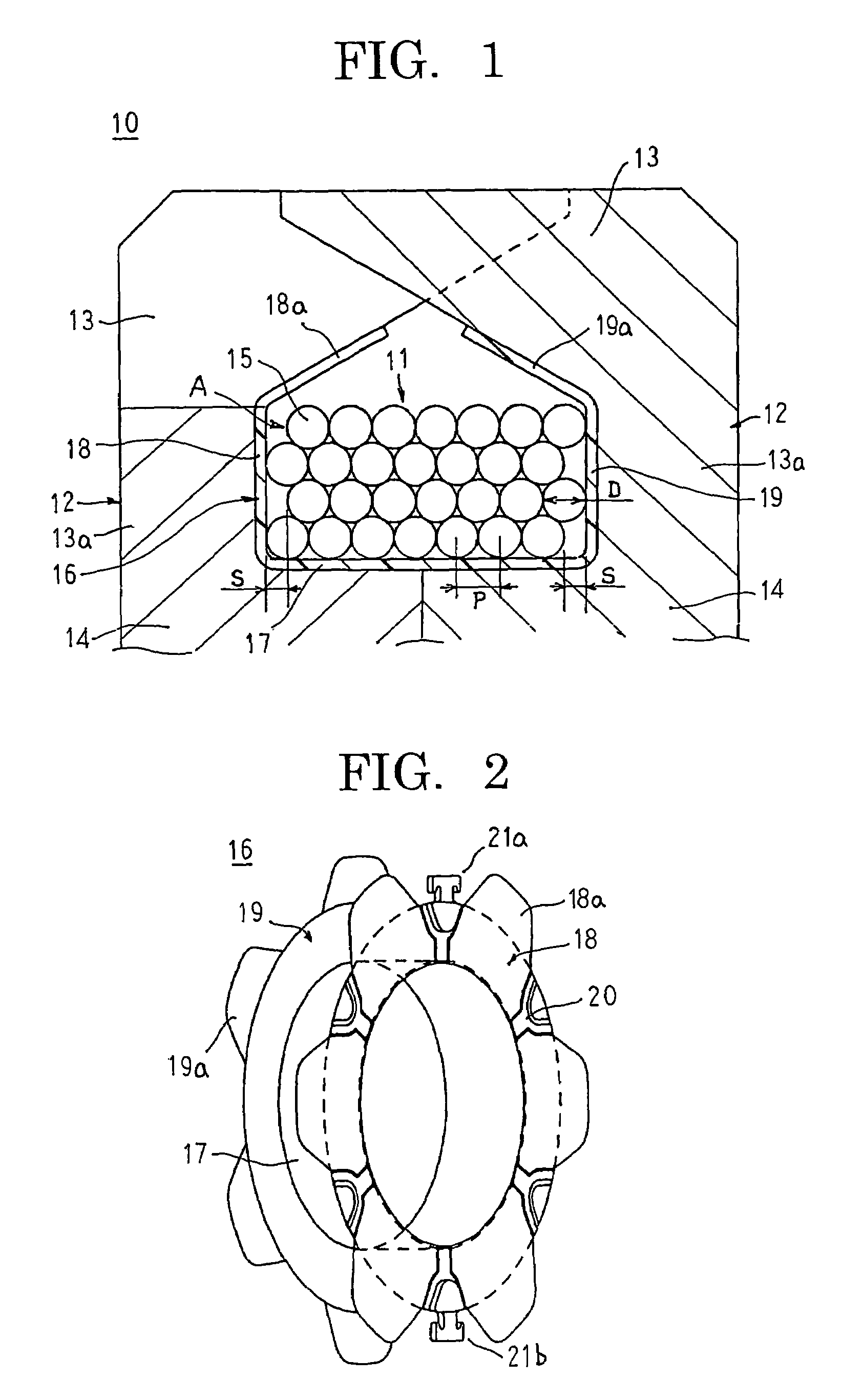
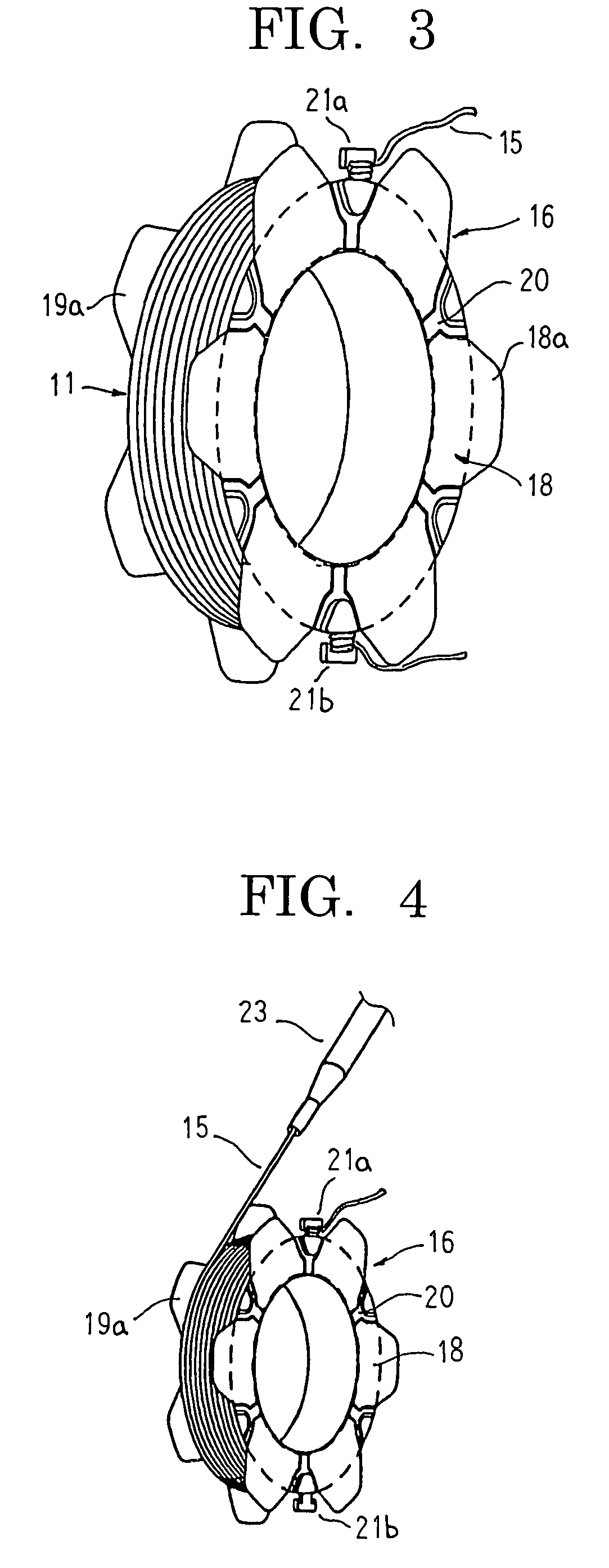
[0026]FIG. 1 is a cross section showing part of a rotor for a rotary electric machine according to Embodiment 1 of the present invention, FIG. 2 is a perspective showing a bobbin used in the rotor for the rotary electric machine according to Embodiment 1 of the present invention, FIG. 3 is a perspective showing a rotor coil installed on the bobbin in the rotor for the rotary electric machine according to Embodiment 1 of the present invention, FIG. 4 is a perspective explaining a method for installing the rotor coil in the rotor for the rotary electric machine according to Embodiment 1 of the present invention, and FIGS. 5 to 7 are process diagrams explaining the method for installing the rotor coil in the rotor for the rotary electric machine according to Embodiment 1 of the present invention. FIGS. 8 to 10 are cross sections showing the rotor coil installed in the rotor for the rotary electric machine according to Embodiment 1 of the present invention, FIG. 8 showing a case in whic...
embodiment 2
[0046]FIG. 11 is a cross section showing a rotor coil installed in a rotor for a rotary electric machine according to Embodiment 2 of the present invention. Moreover, FIG. 11 is a longitudinal section passing through a crossover point C arising when a coil wire 15 is wound into a fourth layer.
[0047]In Embodiment 2, a coil field A of a rotor coil 11, as shown in FIG. 11, is constructed such that a coil wire 15 is installed on a drum portion 17 of a bobbin 16 in four layers of seven columns, and crossover points C do not overlap in a radial direction.
[0048]In odd numbered layers of the coil field A, the coil wire 15 is wound such that a first turn is wound in contact with the inner peripheral wall surface of the first flange portion 18, then a total of seven turns are made at an array pitch P (=D) so as to contact each other, and there is a gap S (=D / 2) between the seventh turn of the coil wire 15 and the inner peripheral wall surface of the second flange portion 19. In even numbered ...
embodiment 3
[0053]FIG. 12 is a plan showing part of a bobbin in a rotary electric machine according to Embodiment 3 of the present invention, and FIG. 13 is a cross section explaining an installed state of a rotor coil in the rotary electric machine according to Embodiment 3 of the present invention.
[0054]In Embodiment 3, as shown in FIG. 12, ridge portions 25a making approximately one turn around a drum portion 17A of a bobbin 16A are disposed at an array pitch of (D+G) in an axial direction on an outer circumferential wall surface of the drum portion 17A. Thus, six guiding grooves 25 partitioned by the ridge portions 15a for guiding coil wire are disposed side by side in an axial direction at an array pitch of (D+G) on the drum portion 17A. An internal shape of each of the guiding grooves 25 is formed so as to be equivalent to an external shape of the coil wire 15. Each of the ridge portions 25a is purposely not formed over a predetermined circumferential range of the drum portion 17A so that...
PUM
| Property | Measurement | Unit |
|---|---|---|
| magnetic | aaaaa | aaaaa |
| diameter | aaaaa | aaaaa |
| thickness | aaaaa | aaaaa |
Abstract
Description
Claims
Application Information
 - R&D
- Intellectual Property
- Life Sciences
- Materials
- Tech Scout
- Unparalleled Data Quality
- Higher Quality Content
- 60% Fewer Hallucinations
Browse by: Latest US Patents, China's latest patents, Technical Efficacy Thesaurus, Application Domain, Technology Topic, Popular Technical Reports.
© 2025 PatSnap. All rights reserved.Legal|Privacy policy|Modern Slavery Act Transparency Statement|Sitemap|About US| Contact US: help@patsnap.com


