
Combination inflator and manifold assembly

a technology of inflator and manifold, which is applied in the direction of rafts, special-purpose vessels, vessel construction, etc., can solve the problems of easy breakage, difficulty in keeping the mob within eyesight, and low value of visual signals during daylight hours, so as to reduce the size and cost of the mob signaling device, prolong the working life of the water-activated bobbin, and prevent humidity

Inactive Publication Date: 2006-06-06
COURTNEY WILLIAM L
View PDF7 Cites 99 Cited by
  • Summary
  • Abstract
  • Description
  • Claims
  • Application Information

AI Technical Summary

Benefits of technology

[0032]Ideally the gas stream maybe pulsed to further conserve compressed gas thereby extending the duration of the signal. Depending on complexity or cost an affordable ½ length tube allows the horn to be thrown without leaking its contents but requires that the cylinder not be filled beyond half full. At an increased cost with compatible with use of a canister carrying maximal contents, a plug operating under gravity occludes the entrance when the aerosol can is in a position other than upright. Dual restricted orifices lead to a chamber filled with mesh and terminated by course filter that provides a large surface area to convert any liquefied gas into gas before passing on to the horn membrane. Alternatively, a ballasted and buoyant flexible drawtube keeps the valve intake above the level of the liquefied gas and can work with the maximum amount of liquefied gas for a longer duration MOBS air horn. After throwing the air horn at the intended victim the MOBS air horn relies upon attached ballast or attached ballast and buoyancy to self-orient the MOBS Air Horn so that the horn's membrane points into the air rather bubble underwater. The Victim can then swim over to the MOBS air horn and convert it back to the manual mode of operation in order to conserve compressed gas thereby extending its life for use in signaling on going search and rescue activities. Alternatively, a combined water activated and manually activated MOBS air horn can be used with infant, infirm or active seamen who might be knocked unconscious by the sailboat's boom immediately prior to being thrown over board
[0083]It is an object of this invention to provide a compressed liquid foam source for creating thermal protection and improved hull tracking performance while providing resilience to puncture and UV fabric failure. In accordance with these and other objects which will become apparent hereinafter, the instant invention will now be described with particular reference to the accompanying drawings.

Problems solved by technology

Traditional boating operation calls for one crew member to do nothing but maintain visual contact with the MOB though this rule is often broken because of a lack of crew.
In a heaving sea it can be very difficult to keep the MOB within eyesight.
While it is required of commercial PFDs that they carry an USCG Approved light with USCG dated batteries, a visual signal is of little value during daylight hours.
If the victim was fortunate enough to have been wearing a PFD when knocked of the vessel it is likely that there is a whistle attached but these do become separated and are easily broken.
If the whistle is found it can be hard to operate and its range is severely restricted compared to the piercing volume of either and oral or compressed gas membrane air horn.
The ambient humidity is such that it is absorbed into the bobbin which over time leads to premature inflation while in the locker or worse at some delicate moment when the wearer is precariously perched on the foredeck of a lunging sailboat while wrestling with a stuck foresail.

Method used


Image

  • Combination inflator and manifold assembly
  • Combination inflator and manifold assembly
  • Combination inflator and manifold assembly

Examples


Embodiment Construction

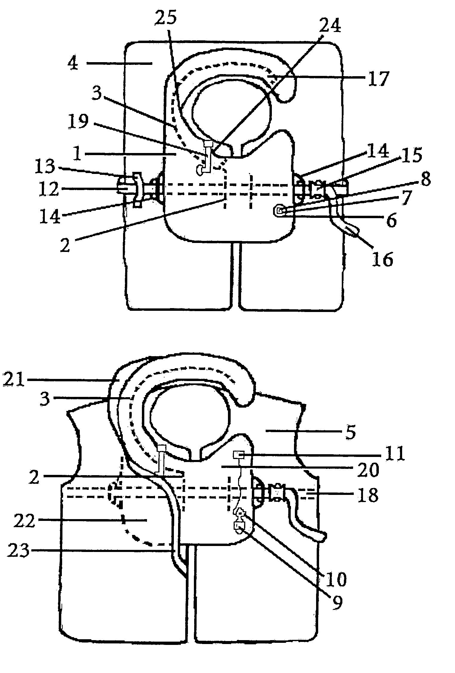
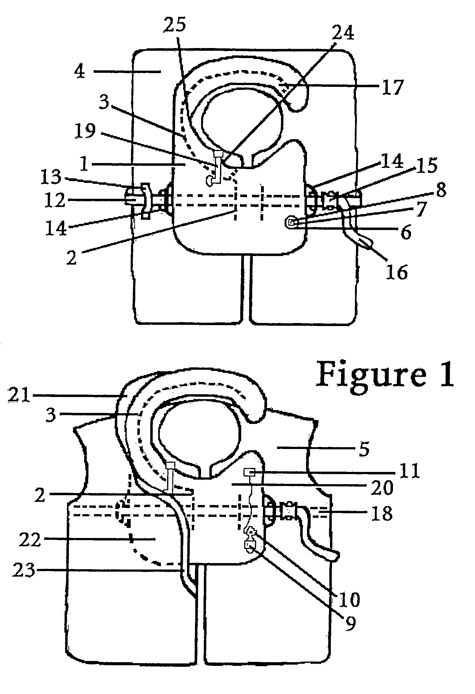
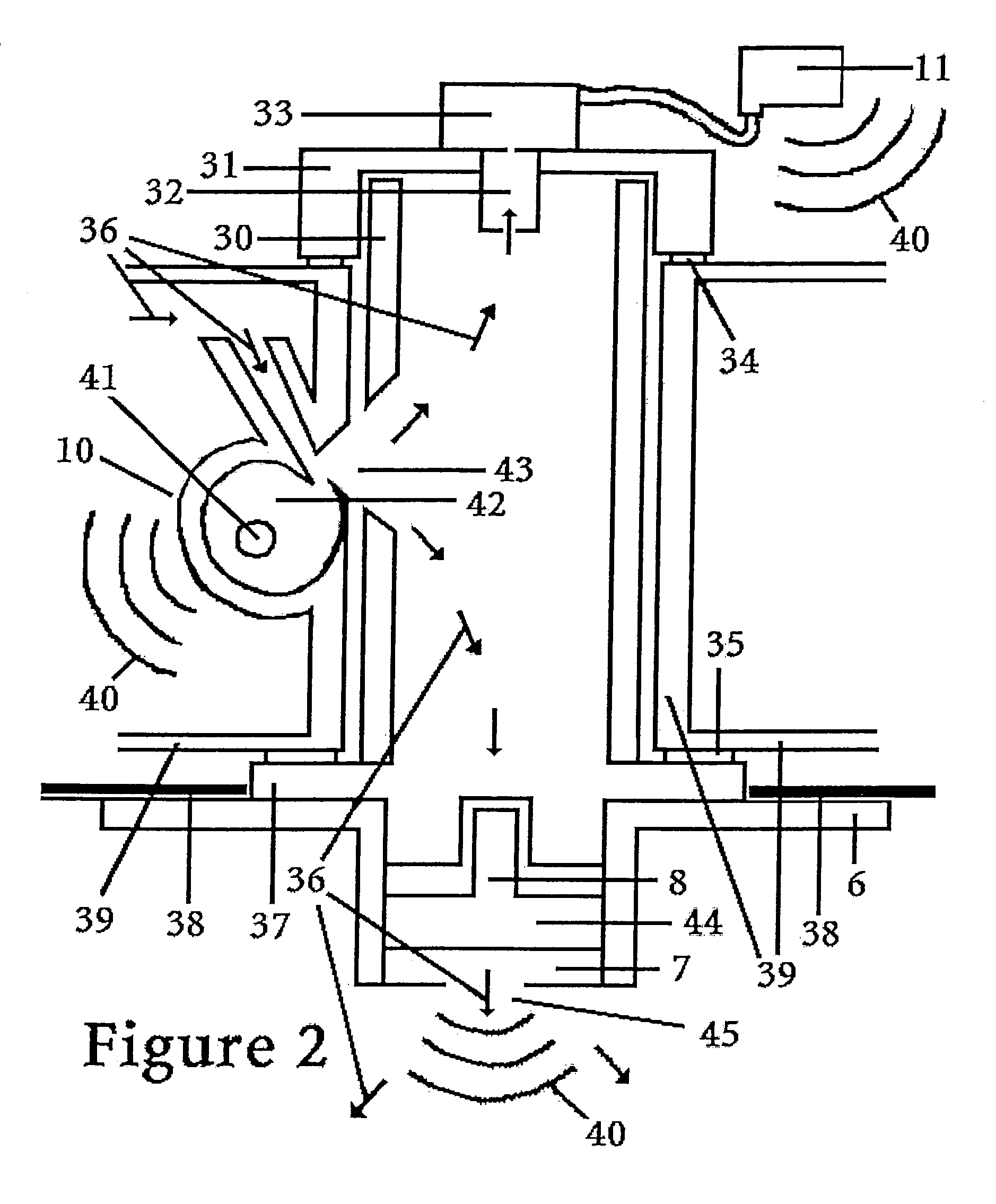
[0141]FIG. 1 demonstrates a simple orally inflated bladder 1 that can be inflated by valve 19 in anticipation of after water entry. Bladder 1 is attached by reversible mounting means 3 along the edge of flange 17 to an inherently buoyant PFD 4. Bladder 1 can be converted from its participation in a highly effective albeit uncomfortable Hybrid PFD (“HPFD”) into an inflatable Garment integrated PFD. Oral bladder 1 is supplied with an integrated CO2 manifold 6 allowing for latter attachment of the compressed gas inflator 10. If the oral bladder 1 is upgraded to include a compressed gas inflator, the previously installed CO2 manifold 6 with integrated oscillator 8, will sound an audible alarm when air is passed through the CO2 manifold during inflation regardless of the type or manufacture of the inflator that is attached.

[0142]Use of bladder fabric, which is laminated on only one side, requires creating an attachment flange 2. A reduction weld takes a tuck out of the backside of the bl...


PUM


Abstract

A variable volume raft containing adjustable ratio and amounts of air and or water. The buoyancy and ballast of the raft are routinely adjusted to accommodate additional occupants and changing weather conditions. A manual pump can be the primary or back up source for initial inflation. The torque pump twisted by hand or amplified by a lever arm generates air pressure for maintenance and repairing deflating lacerations at sea. The pumps collector gathers and pressurizes rain water for drinking in one chamber while pressurizing sea water as a stabilizing ballast in another chamber. A double hull or full floor chamber allows huge variations in buoyancy or ballast as dictated by changing needs for stability versus mobility. A compressed liquid or two-part foam confers puncture resistance to a portion of the raft. A thrown self-righting manual air horn, worn water-activated air horns and water activated transmitted signals, mark the site for rescuers.

Description

[0001]This application claims priority to and the benefit of U.S. Provisional Application Ser. No. 60 / 449,992, filed on Feb. 25, 2003 (entitled “Throw-able or Wearable, Self-Orienting, Manual or Water Activated Air Horn for Signaling a Man Over Board”) and U.S. Provisional Application Ser. No. 60 / 370,585, filed Apr. 5, 2002 (both applications are incorporated by reference).BACKGROUND OF THE INVENTION[0002]1. Field of the Invention[0003]The present invention relates to life rafts, flotation aids and signaling devices for the man over board. More particularly to the use of manual means of pneumatic and hydraulic manipulation of chambers, floors or hulls of the life raft whose volume can now be continuously adjusted to meet changes in occupant load, weather conditions and availability or rain water to be stored for drinking. The present invention also relates to the provision of airway protective flotation aids, multi-modal thrown, self orienting manual and water activated signaling de...

Claims


Application Information

Patent Timeline
IPC IPC(8): B63C9/125B63B7/08B63C9/00B63C9/04B63C9/06B63C9/18B63C9/19B63C9/20
CPCB63C9/0005B63C9/02B63C9/04B63C9/18B63C9/20B63C9/24B63C9/1255B63B2201/02B63C2009/044B63C2009/0094
Inventor COURTNEY, WILLIAM L.
Owner COURTNEY WILLIAM L
Learn More