Optical transmission apparatus with directionality and divergence control

a technology of optical transmission apparatus and directionality, applied in the field of optical enhancement of light transmission, can solve the problems of reducing the practicality of the apparatus comprising a small aperture, namely diffraction, and reducing the practicality of such an apparatus for many, and achieves enhanced light transmission, low optical divergence output light, and enhanced transmission

Inactive Publication Date: 2006-06-06
UNIV LOUIS PASTEUR ULP +1
View PDF2 Cites 51 Cited by
  • Summary
  • Abstract
  • Description
  • Claims
  • Application Information

AI Technical Summary

Benefits of technology

[0039]A still further object of the present invention is to provide a near-field scanning optical microscope probe with one or more apertures which provides a more focused output light beam with improved enhanced t

Problems solved by technology

Whether an apparatus comprises enhanced transmission or not through an aperture, there is an additional problem which reduces the practicality of the apparatus comprising a small aperture, namely diffraction.
These f

Method used


Image

  • Optical transmission apparatus with directionality and divergence control
  • Optical transmission apparatus with directionality and divergence control
  • Optical transmission apparatus with directionality and divergence control

Examples


Embodiment Construction

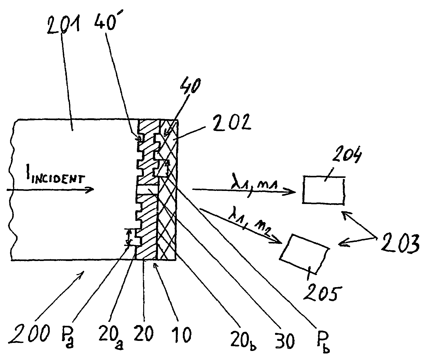
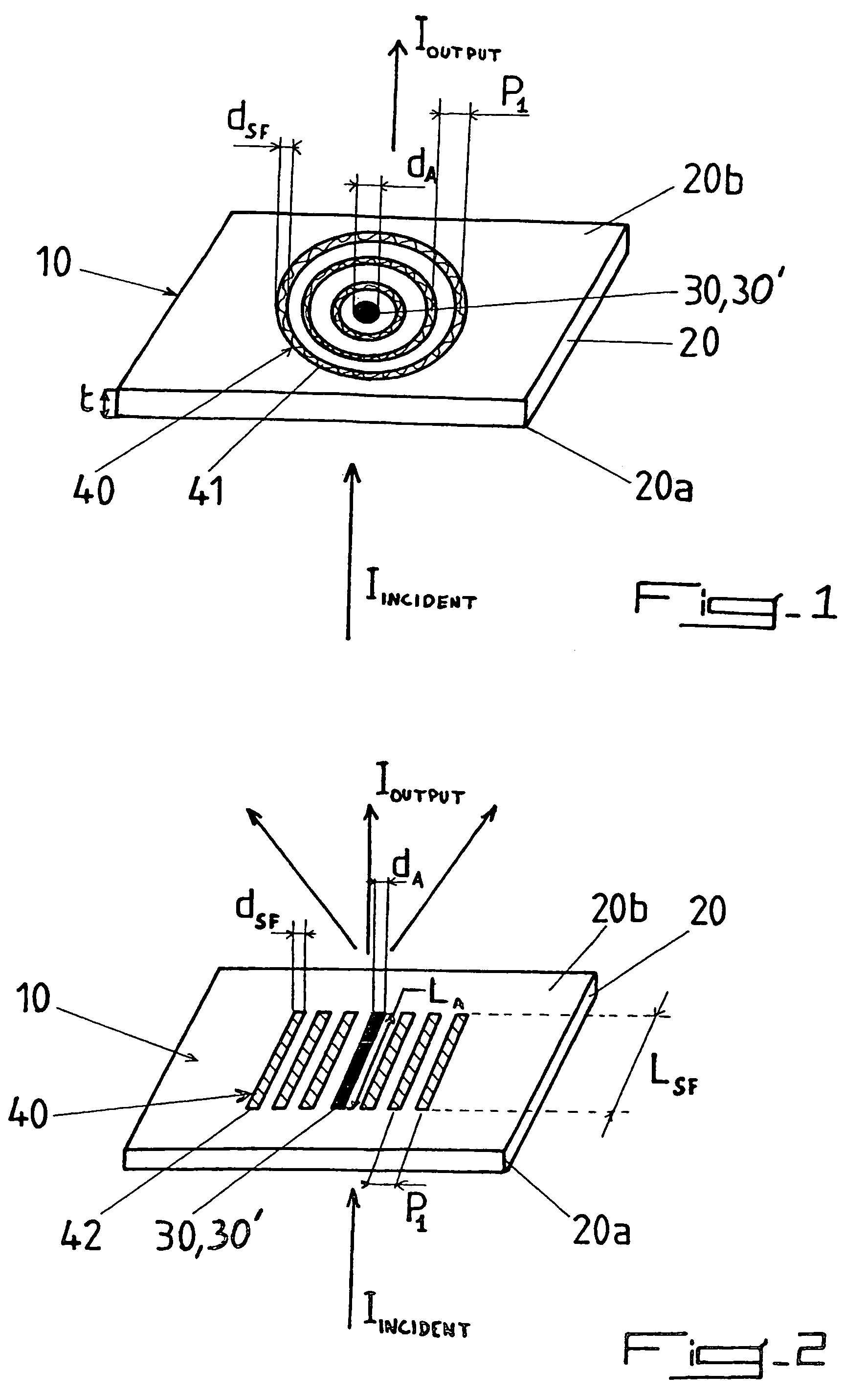
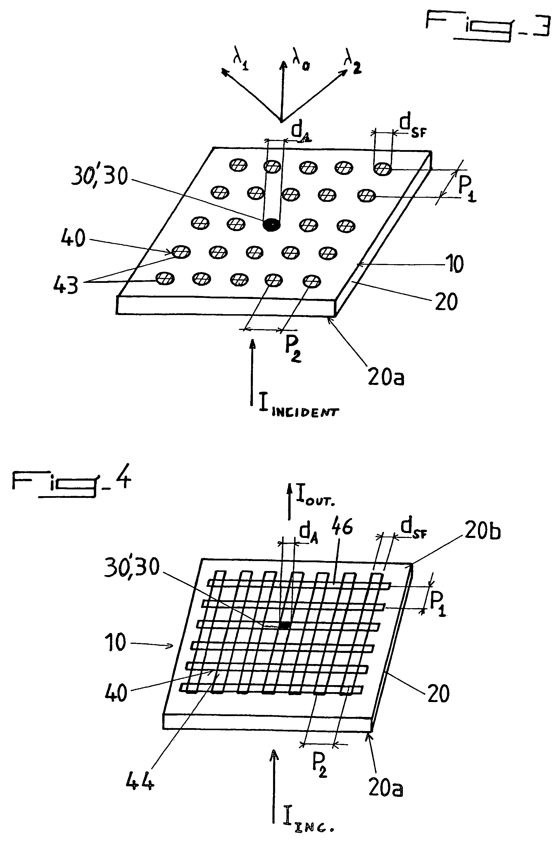
[0077]Referring now to the enclosed figures, FIGS. 1 to 5 illustrate (not necessarily to scale) several illustrative embodiments of an enhanced light transmission apparatus with directionality and divergence control 10 of the present invention. Generally speaking, said apparatus 10 includes a surface structure in the form of a thin metal plate or thin metal film 20 having a first surface 20a and a second surface 20b. The metal film 20 has at least one aperture or hole 30 with an exit opening 30′ provided therein, and at least the surface 20b from which the light exits includes a periodic surface topography as will be described below. Prior to describing particular embodiments of the invention, it will be useful to elaborate upon several terms which are important for understanding the invention.

[0078]Metal film 20 forming the surface structure may comprise a metal film or a metal plate. The material comprising metal film 20 may be any conductive material, such as any metal or a doped...


PUM


Abstract

An apparatus for emitting light with a controlled directionality and optical divergence from at least one opening includes a light impervious surface structure having the at least one opening, a periodic or quasi-periodic surface topography including one or several surface feature(s) and associated with the at least one opening on the surface structure, whereby light emerging from the opening(s) interacts with surface waves on the surface structure (20) thereby providing controlled directionality and optical divergence of the emitted light.

Description

CROSS REFERENCE TO RELATED APPLICATIONS[0001]This is the 35 USC 371 National Stage of International Application PCT / EP02 / 11047 filed on Aug. 30, 2002, which designated the United States of America. International Application PCT / EP02 / 11047 claims priority of U.S. Application No. 60 / 316,247, filed on Aug. 31, 2001, the entire contents of which are hereby incorporated by reference.FIELD OF THE INVENTION[0002]The present invention relates to the field of optics, and in particular to the enhanced transmission of light through or from a surface structure, such as a metal film, with one or more openings or apertures.BACKGROUND OF THE INVENTION[0003]As discussed in detail in U.S. Pat. No. 6,236,033 to Ebbesen et al., the optical transmission of a single, sub-wavelength aperture in a metal film can be strongly enhanced when the incident light is resonant with surface waves, such as surface plasmons, at the film's surface. In order to couple the incident radiation to the surface waves, the su...

Claims


Application Information

Patent Timeline
IPC IPC(8): H01J5/16G02B5/18G02B5/20G02B27/56
CPCB82Y20/00B82Y35/00G01Q60/22G02B27/56G02B5/1828G02B5/203G02B5/008
Inventor LEZEC, HENRI JOSEPHEBBESEN, THOMAS WREN
Owner UNIV LOUIS PASTEUR ULP
Why Eureka
Try Eureka