Multiplier-divider circuit for a PFC controller

a technology of multiplier divider and power factor correction, which is applied in the field of analog multiplier divider for power factor correction (pfc) circuit, can solve the problems of inconvenient bipolar circuit manufacturing, high cost, and inability to meet the requirements of bipolar devices, and achieve the effects of low temperature coefficient, low cost, and small die siz

Active Publication Date: 2006-06-06
SEMICON COMPONENTS IND LLC
View PDF2 Cites 35 Cited by
  • Summary
  • Abstract
  • Description
  • Claims
  • Application Information

AI Technical Summary

Benefits of technology

[0021]Another objective of the present invention is to provide an analog multiplier-divider that is manufactured using CMOS fabrication. The multiplier-divider according to the present invention exclusively uses MOSFET-based devices. Therefore, the multiplier-divider according to the present invention can be manufactured at a significantly smaller die-size, and at a lower cost, than the prior-art multiplier-dividers.
[0022]Another objective of the present invention is to provide an analog multiplier-divider having a characteristic equation that is substantially temperature-independent, compared to the prior-art multiplier-divider. The multiplier-divider according to the present invention is constructed with MOSFET-devices. Thus, the temperature coefficient of the multiplier-divider according to the present invention is low. The multiplier-divider according to the present invention can operate successfully over a very wide temperature range.
[0023]Another objective of the present invention is to provide an analog multiplier-divider with reduced power consumption. The multiplier-divider according to the present invention does not require a constant biasing current.
[0024]Another objective of the present invention is to provide an analog multiplier-divider with improved noise immunity. The accuracy of the output signal of the multiplier-divider according to the present invention is not significantly affected by small noise components from the input signals.

Problems solved by technology

They all share the same disadvantages, to the extent that they are built using bipolar transistor devices.
One disadvantage of the prior-art multiplier-divider shown in FIG. 2 is that it is a bipolar device.
For many present-day applications, such as PFC circuits, integrated circuits manufactured using a bipolar process are not suitable, because their die-size are too large and the cost is too high.
Another disadvantage of the prior-art multiplier-divider shown in FIG. 2 is that the output of the circuit varies significantly with temperature.
Thus, the output of the circuit is highly susceptible to temperature changes.
Another disadvantage of the prior-art multiplier-divider shown in FIG. 2 is high power consumption.
This results in significant power consumption.
Another disadvantage of the prior-art multiplier-divider shown in FIG. 2 is poor noise immunity.
With such devices, even relatively small input signal distortion can result in significant output signal distortion.
Another disadvantage of the prior-art multiplier-divider shown in FIG. 2 is that it has a narrow input range, limited to the linear operating region of bipolar transistors.
Outside of this narrow input range, the multiplier-divider shown in FIG. 2 is highly susceptible to distortion.

Method used


Image

  • Multiplier-divider circuit for a PFC controller
  • Multiplier-divider circuit for a PFC controller
  • Multiplier-divider circuit for a PFC controller

Examples


Embodiment Construction

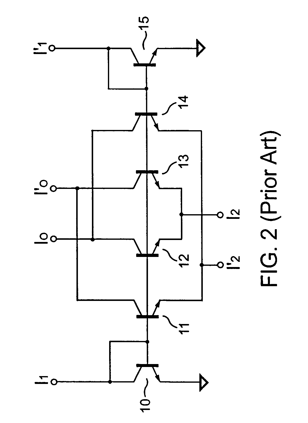
[0036]Referring now to the drawings wherein the contents are for purposes of illustrating the preferred embodiment of the invention only and not for purposes of limiting same, FIG. 2 shows a prior-art multiplier-divider.

[0037]The prior-art multiplier-divider is constructed with an array of six bipolar transistors. The multiplier-divider includes six transistors 10, 11, 12, 13, 14 and 15. A base of each of the transistors 10, 11, 12, 13, 14 and 15 are tied together.

[0038]A collector of the transistor 10 is connected to the base of the transistor 10. An emitter of the transistor 10 is connected to a ground reference. The collector of the transistor 10 is connected to a first positive input terminal I1. A collector of the transistor 11 is connected to a negative output terminal I′O. A collector of the transistor 12 is connected to a positive output terminal IO. A collector of the transistor 13 is connected to the negative output terminal I′O. An emitter of the transistor 12 and an emit...


PUM


Abstract

The present invention introduces an integrated analog multiplier-divider circuit. The multiplier-divider block according to the present invention is ideal for use in the power factor correction (PFC) controllers of many switch-mode power supplies. The analog multiplier-divider according to the present invention is built with CMOS devices. Because of this, it has many advantages over prior-art multiplier-dividers. One important advantage is that the die-size and the cost can be reduced. Another important advantage of the multiplier-divider according to the present invention is substantially reduced temperature dependence.

Description

BACKGROUND OF THE INVENTION[0001]1. Field of the Invention[0002]The present invention relates to the art of power supplies, and in particular to an analog multiplier-divider for a power factor correction (PFC) circuit.[0003]2. Description of the Prior Art[0004]There are many uses for analog multiplier-dividers in modern electronics. Multiplier-dividers produce an output signal that is proportional to a ratio of two or more input signals. The input and output signals can either be voltages or currents.[0005]One common use of multiplier-dividers is in power factor correction (PFC) circuits. PFC circuits commonly use multiplier-dividers to generate a control signal based on the input current, the feedback signal, and the input voltage. FIG. 1 demonstrates the use of an analog multiplier-divider in a PFC circuit.[0006]There are many known ways of constructing analog multiplier-dividers, such as logarithmic amplifiers and antilog amplifiers. The implementation of a logarithmic amplifier ...

Claims


Application Information

Patent Timeline
Patent Type & Authority Patents(United States)
IPC IPC(8): G06G7/12G05F1/40H02M1/00H02M1/42
CPCH02M1/4208H02M1/4225H02M1/32Y02B70/126H02M2001/0012Y02B70/10Y02P80/10H02M1/0012
Inventor YANG, TA-YUNGLIN, SONG-YIHSUEH, CHENG-CHI
Owner SEMICON COMPONENTS IND LLC
Why Eureka
Try Eureka