
Image amplification for laser systems

a laser system and laser technology, applied in lasers, recording devices, printers, etc., can solve the problems of short shelf life, low contrast ratio, and lower productivity

Inactive Publication Date: 2006-06-06
NORSELD
View PDF13 Cites 14 Cited by
  • Summary
  • Abstract
  • Description
  • Claims
  • Application Information

AI Technical Summary

Problems solved by technology

However, even this figure is only achieved in special formulations that are expensive, have short shelf life and a low contrast ratio.
Exposure times become critical but increasing exposure periods will lead to lower productivity.
Finding a suitable combination of laser frequency, power, resists and working rate that matches all of the above characteristics is the challenge at hand for LDI systems designers.

Method used


Image

  • Image amplification for laser systems
  • Image amplification for laser systems
  • Image amplification for laser systems

Examples


Embodiment Construction

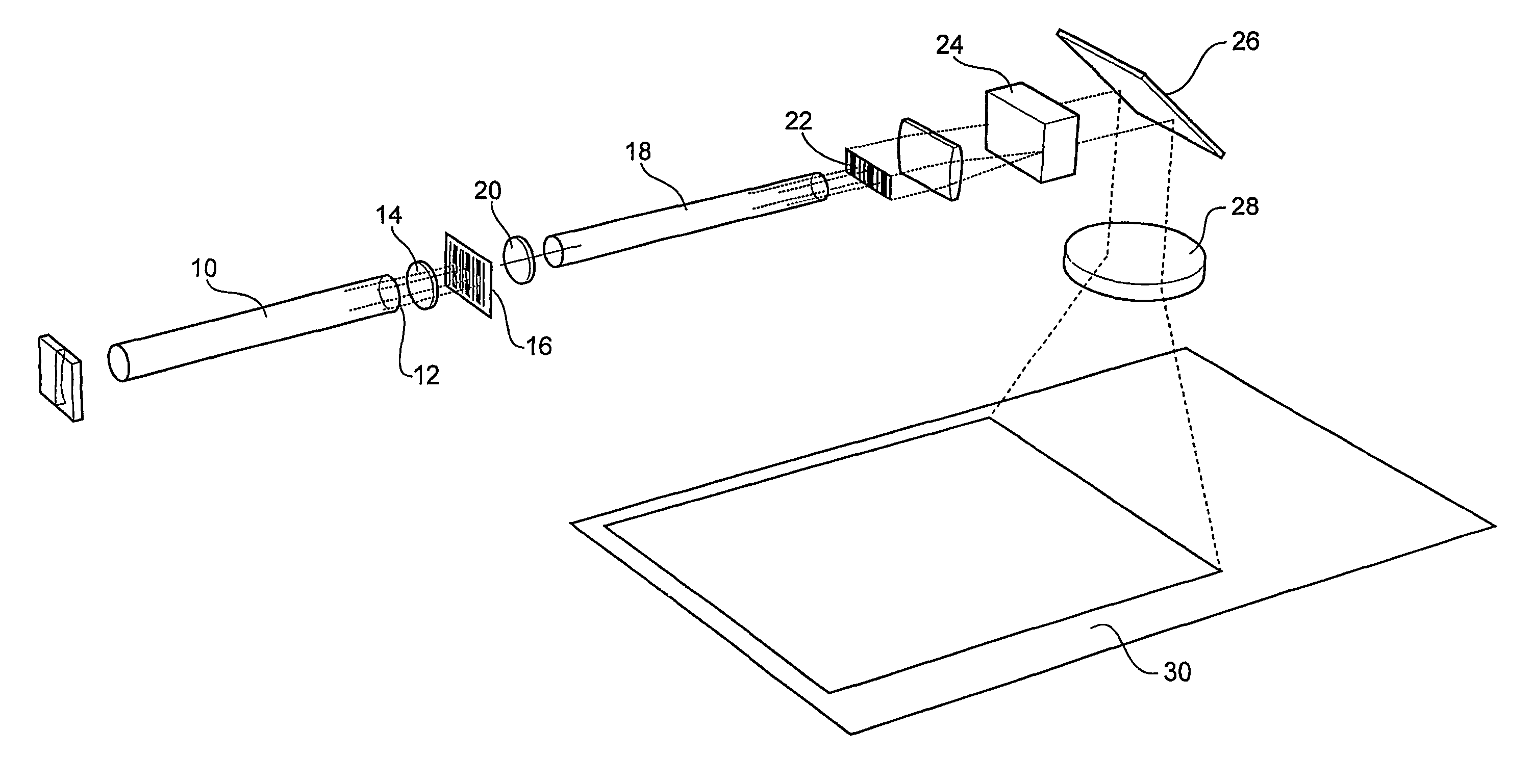
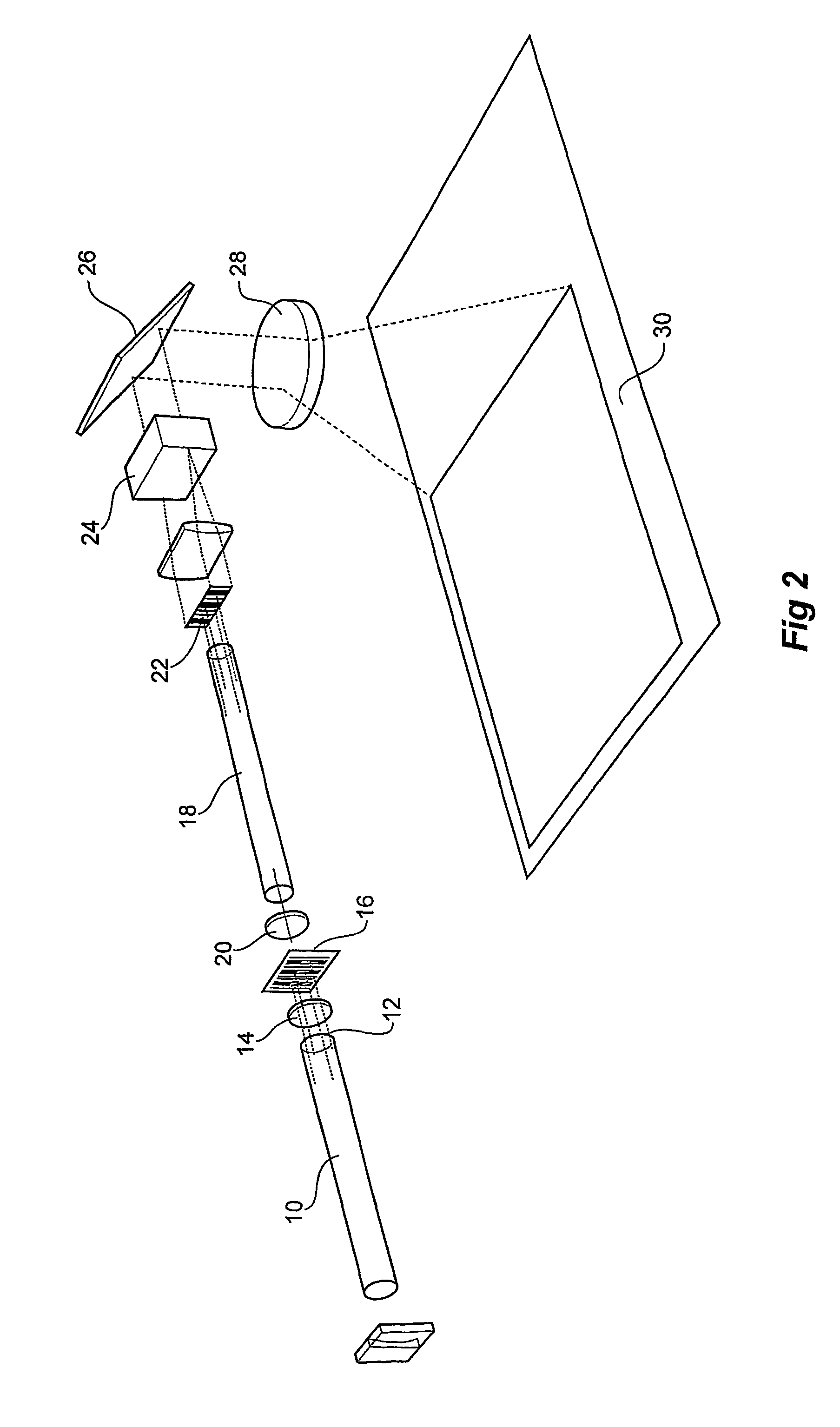
[0032]In an embodiment of the invention a copper bromide (CuBr) laser is used as the oscillator 10, as is pictorially represented in FIG. 2. Such lasers are known for their relatively high power and excellent beam quality, and very high optical gain.

[0033]However, in this embodiment of the invention a relatively low power output is only needed to be generated at 12 and directed to an optical system 14 that further adapts the laser output to illuminate the active area of the image forming device. The components and their arrangement in this part of the apparatus are well known to those skilled in the art.

[0034]The wavelength of the copper bromide laser output is 511 nm and 578 nm (a green and yellow laser) and can be designed to give low power (16. The spatially modulated beam now in the form of a partial image of the printed circuit board feature information is now collimated by the optical system 20 and amplified by the second laser tube 18 to form a high power image containing man...


PUM

PropertyMeasurementUnit
wave lengthsaaaaaaaaaa
wavelengthaaaaaaaaaa

Abstract

An optical image amplifier comprising a copper bromide laser (10) to provide a source of optical radiation, an optical amplifier (18) for amplifying the optical radiation received from the laser (10), an optical image forming device (16) located intermediate the laser (10) and optical amplifier (18) for forming an image to spatially modulate the output of the laser (10), and optical focusing means (22) located at the output of the optical amplifier for translating the image or a portion thereof to a surface to be illuminated (30). The system increases the efficiency of irradiation of photo-sensitive films, used for example in the manufacture of integrated circuits and printed circuit boards using laser direct imaging.

Description

[0001]This invention relates to the intensity amplification of images and in particular the use of copper bromide lasers to do so. In one particular embodiment such an arrangement is useable for laser direct imaging.BACKGROUND[0002]The science of laser amplification is known and a multitude of scientific uses exists for such devices and in the industrial / commercial arena (optical fibre laser transmission for communications etc).[0003]Use of lasers and in particular metal vapour and copper bromide lasers is also known, their use being equally diverse in the scientific industrial / commercial and medical fields.[0004]Copper bromide lasers are additionally known for their very high optical brightness gain (approx 10,000).[0005]One application that appears particularly suitable for the use of a laser occurs in the relatively new field of Laser Direct Imaging (LDI).[0006]Forming an image on a photo sensitive film referred to generally as photo-lithography. It is commonly employed to expose...

Claims


Application Information

Patent Timeline
Patent Type & Authority Patents(United States)
IPC IPC(8): H01S3/22H01S3/00G03F7/20H01S3/227
CPCG03F7/2053G03F7/70025G03F7/704H01S5/50H01S3/227H01S3/2375
Inventor DAVIS, PETER ERIC
Owner NORSELD
Learn More