Optical modulator

a modulator and optical technology, applied in the field of optical modulators, can solve the problems of high drive voltage, shortening the distance between the signal electrode and the waveguide, and causing the change (wavelength chirping) of the modulated light to degrade the signal waveform after transmission

Inactive Publication Date: 2006-06-06
FUJITSU LTD
View PDF3 Cites 18 Cited by
  • Summary
  • Abstract
  • Description
  • Claims
  • Application Information

AI Technical Summary

Benefits of technology

[0017]In the optical modulator of the above configuration, the light incident on the optical waveguide is branched into two lights by the branching section, to be respectively sent to the pair of parallel waveguides. An electric field generated between the signal electrode and the earth electrode according to the electric signal being propagated through the signal electrode is applied on the parallel waveguides, and the refractive index of each of the parallel waveguides is changed due to an electro-optic effect by this electric field so that phases of the lights being propagated through the parallel waveguides are changed respectively. At this time, since the polarization inversion region and the non-inversion region whose polarization directions are opposite to each other are formed in the interaction portion and the arrangement of the signal electrode for the pair of parallel waveguides is changed in each region, a difference between phase change amounts of the lights being propagated through the parallel waveguides is offset, so that the wavelength chirping caused in modulated lights to be multiplexed in the multiplexing section is reduced.

Problems solved by technology

However, the conventional Mach-Zehnder optical modulator as described above has a following problem related to the wavelength chirping.
As a result, there is caused a problem in that absolute values of phase changes in the respective lights being propagated through the parallel waveguides 113A and 113B are varied, and when a signal is switched from “0” to “1” or from “1” to “0”, a wavelength change (wavelength chirping) in the modulated light is caused to degrade a signal waveform after transmitted.
However, since it is impossible to arrange the parallel waveguides just below the signal electrode, there is a drawback in that a distance between the signal electrode and the waveguide is lengthened, and accordingly, a high drive voltage needs to be applied.
Further, in the case where the two signal electrodes are used to perform the push-pull driving, since two connectors for inputting the high frequency electric signal are necessary, and also electric signals whose data is inverted to each other need to be applied on both of the signal electrodes while phases thereof being controlled, there is a drawback in that a circuit configuration of driving system becomes complicated.
However, the polarization inversion optical modulator described above has basically an optical waveguide structure different from that of the Mach-Zehnder optical modulator, and therefore, does not solve the problems of wavelength chirping as described above.

Method used


Image

  • Optical modulator
  • Optical modulator
  • Optical modulator

Examples


first embodiment

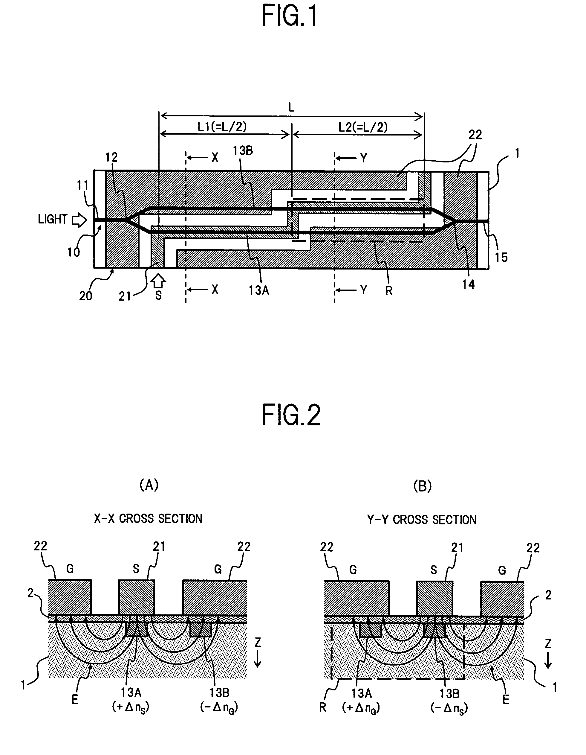
[0032]FIG. 1 is a plan view showing a configuration of a Mach-Zehnder optical modulator according to the present invention. Further, FIG. 2 is a diagram showing an essential structure of a cross section in each part of FIG. 1, in which (A) is an X—X cross section and (B) is a Y—Y cross section.

[0033]In FIG. 1 and FIG. 2, the optical modulator in the present embodiment comprises a substrate 1 which has an electro-optic effect and is provided with a region R whose polarization direction is inverted, an optical waveguide 10 of branching interference type formed on the surface of the substrate 1, and a coplanar electrode 20 formed on the surface of the substrate 1 via a buffer layer 2.

[0034]The substrate 1 is configured such that the known processing such as the titanium (Ti) diffusion or the proton exchange is performed on a Z-cut LiNbO3 substrate or the like, to form the optical waveguide 10, and thereafter, the polarization direction of the region R (region encircled by broken line i...

second embodiment

[0048]Next, the present invention will be described.

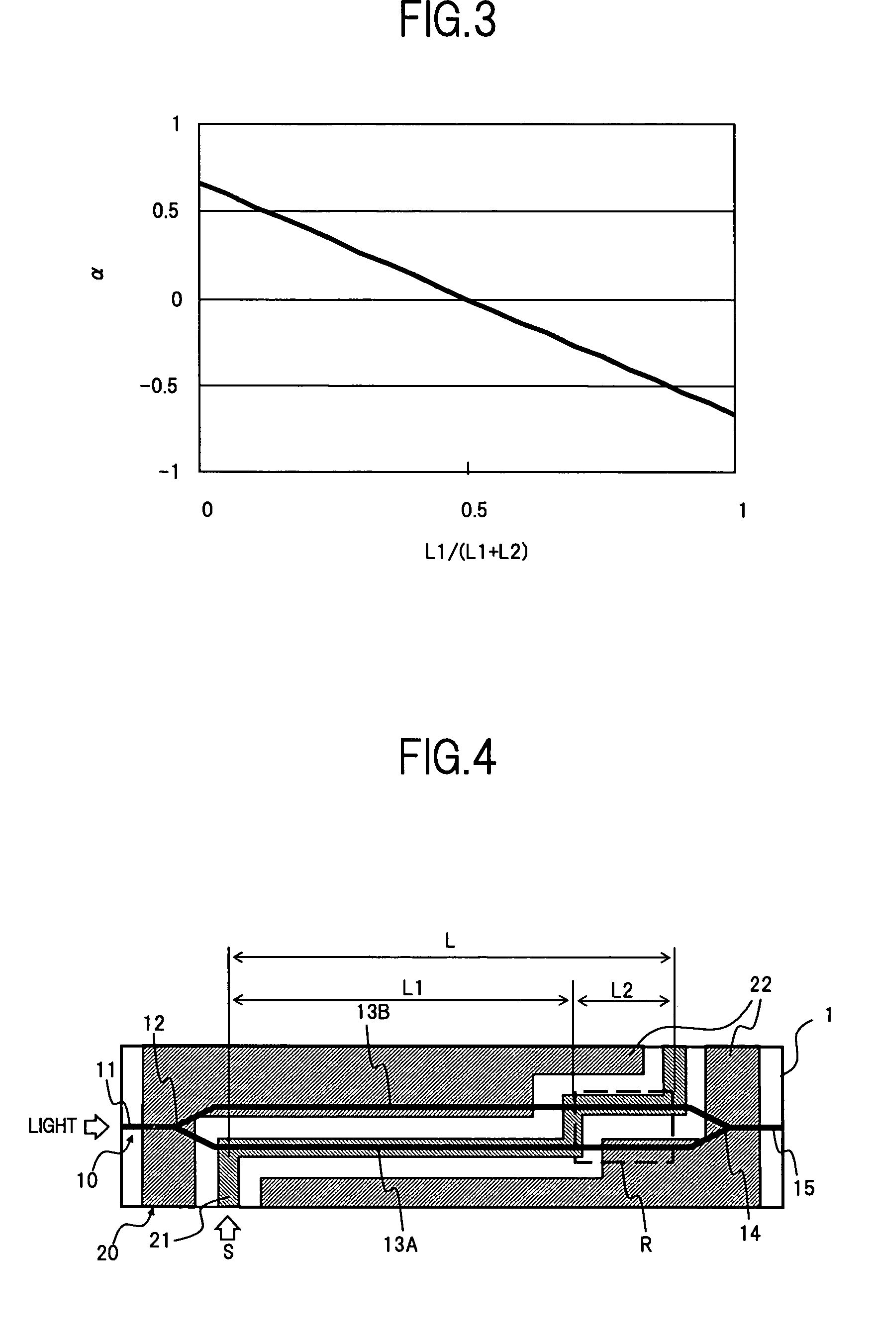
[0049]In the above described first embodiment, the length of the polarization inversion region R has been designed for the purpose of suppressing the wavelength chirping caused in the Mach-Zehnder optical modulator to approximately zero. However, there is a case where a required value of the wavelength chirping is not zero, depending on systems to which the present optical modulator is applied. Therefore, in the second embodiment, an optical modulator corresponding to the above case will be described.

[0050]FIG. 4 is a plan view showing a configuration of a Mach-Zehnder optical modulator in the second embodiment.

[0051]In FIG. 4, the configuration of the present Mach-Zehnder optical modulator differs from the configuration in the first embodiment shown in FIG. 1 in that the length L2 in the polarization direction of the light of the polarization inversion region R formed on the substrate 1 is modified according to a value of the wave...

third embodiment

[0055]Next, the present invention will be described.

[0056]FIG. 5 is a plan view showing a configuration of a Mach-Zehnder optical modulator in the third embodiment.

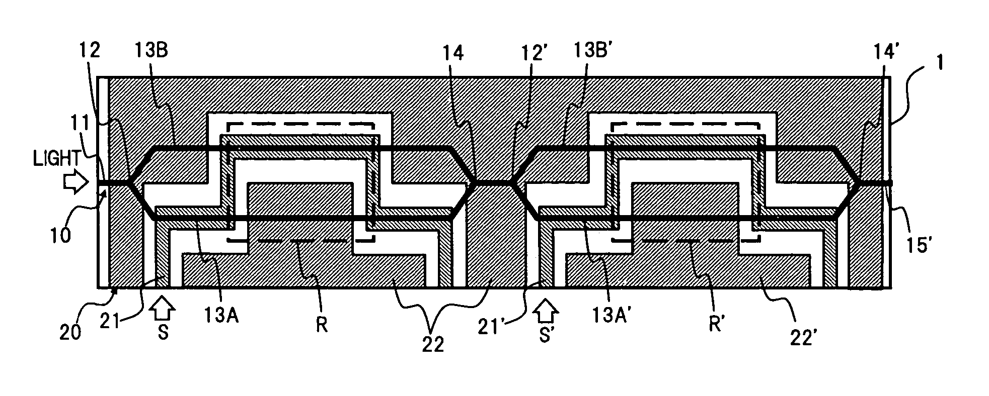
[0057]In FIG. 5, the configuration of the present Mach-Zehnder optical modulator differs from the configuration in the first embodiment shown in FIG. 1 in that the polarization inversion region R is formed on the center portion in the lengthwise direction of the interaction portion on the substrate 1 so that the non-inversion regions are formed on the front and rear portions (the left and right sides in FIG. 5) of the polarization inversion region R, and the patterning of the coplanar electrode 20 is modified so that the signal electrode 21 is positioned on the parallel waveguide 13A in the non-inversion regions and is positioned on the parallel waveguide 13B in the polarization inversion region R. The configuration other than the above is similar to the configuration in the first embodiment, and accordingly, the descript...


PUM

PropertyMeasurementUnit
thicknessaaaaaaaaaa
lengthaaaaaaaaaa
total lengthaaaaaaaaaa

Abstract

The present invention has an object to provide a Mach-Zehnder optical modulator for achieving the reduction of wavelength chirping caused in a modulated light. To this end, according to the present invention, in a Mach-Zehnder optical modulator configured by forming an optical waveguide and a coplanar electrode on a substrate having an electro-optic effect, a polarization inversion region is formed on a part of a portion where lights being propagated through a pair of parallel waveguides and a high frequency electric signal being propagated through a signal electrode interact to each other, and also the signal electrode is arranged on one of the parallel waveguides in the polarization inversion region and is arranged on the other parallel waveguide in a non-inversion region.

Description

[0001]This application is a continuation of PCT / JP02 / 12824, filed on Dec. 6, 2002.BACKGROUND OF THE INVENTION[0002]1. Field of the Invention[0003]The present invention relates to an optical modulator used for an optical communication, and in particular, to a Mach-Zehnder optical modulator using an optical waveguide.[0004]2. Description of the Related Art[0005]For example, as optical waveguide devices using an electro-optic crystal such as lithium niobate (LiNbO3), lithium tantalate (LiTaO2) or the like, a variety of functional devices is formed such that a metallic film is formed on a part of a crystal substrate, to be thermally diffused or to be patterned, then, is proton exchanged in benzoic acid so that an optical waveguide is formed, and thereafter, an electrode is disposed in the vicinity of the optical waveguide. As one of optical waveguide devices using the electro-optical crystals, there has been known a Mach-Zehnder optical modulator having an optical waveguide structure of...

Claims


Application Information

Patent Timeline
Patent Type & Authority Patents(United States)
IPC IPC(8): G02F1/295G02F1/03G02F1/225
CPCG02F1/2255G02F1/0316
Inventor SUGIYAMA, MASAKIDOI, MASAHARU
Owner FUJITSU LTD
Why Eureka
Try Eureka