Liquid milk freeze/thaw apparatus and method

Inactive Publication Date: 2006-06-13
ZEVLAKIS ANASTASSIA
View PDF45 Cites 38 Cited by
  • Summary
  • Abstract
  • Description
  • Claims
  • Application Information

AI Technical Summary

Benefits of technology

[0014]It is therefore an object of the present invention to provide super-cooled ice cubes, formed of vari

Problems solved by technology

Since the “thaw” cycle has very high heating power causing a high temperature difference between the heated tray surface and the ice segment, this cycle is short, and the heating of

Method used


Image

  • Liquid milk freeze/thaw apparatus and method
  • Liquid milk freeze/thaw apparatus and method
  • Liquid milk freeze/thaw apparatus and method

Examples


Embodiment Construction

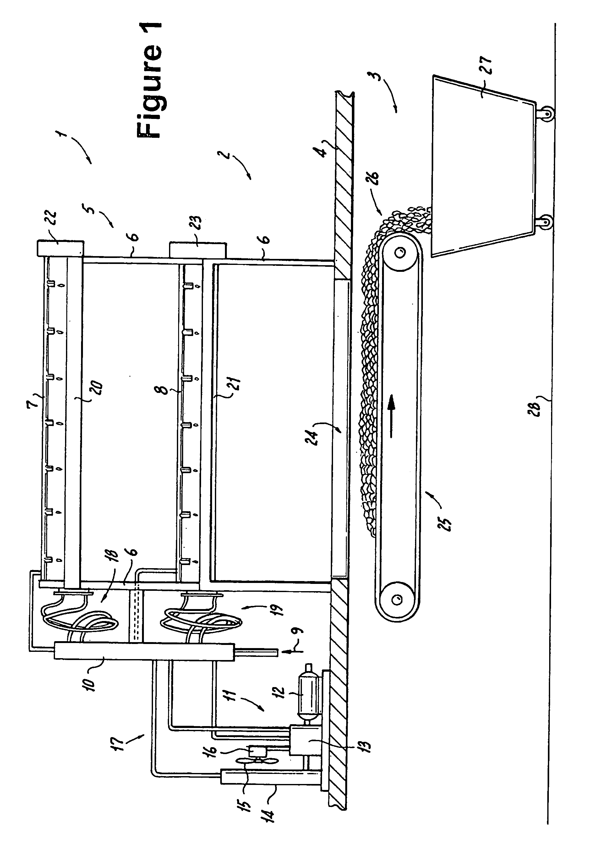
[0080]FIG. 1 presents an illustration of an embodiment of this invention as a complete ice making system 1 housed on an upper floor 2 and a lower floor 3 of a building. The ice making apparatus 5 rests on support floor 4, which has a large opening communicating with the floor 3 below. Under this opening is conveyor belt 25 which moves dumped ice segments 26 to bin 27 which rests on the lower floor surface 28. A vapor compression refrigeration system 11 (part of ice making apparatus 5) includes compressor motor 12, compressor 13, fan motor 16, fan 15, heat exchanger 14, and rigid refrigerant lines 17.

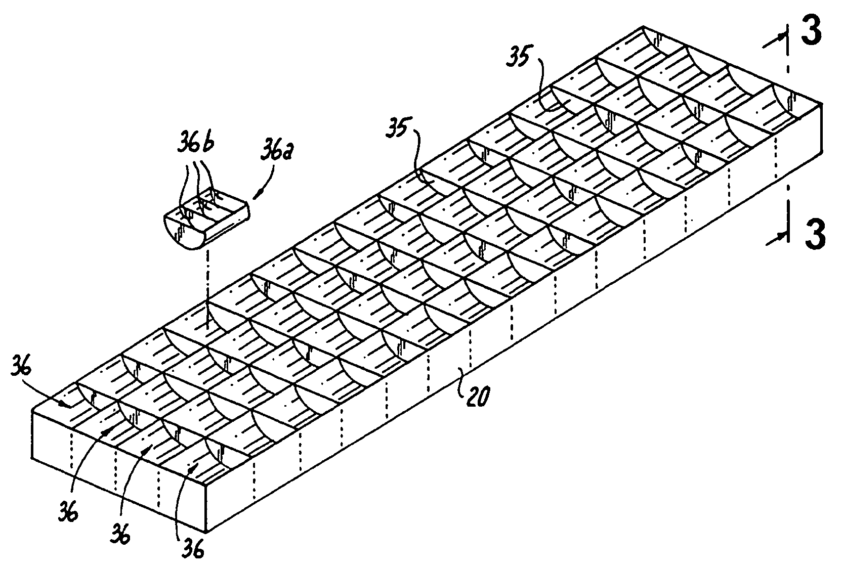
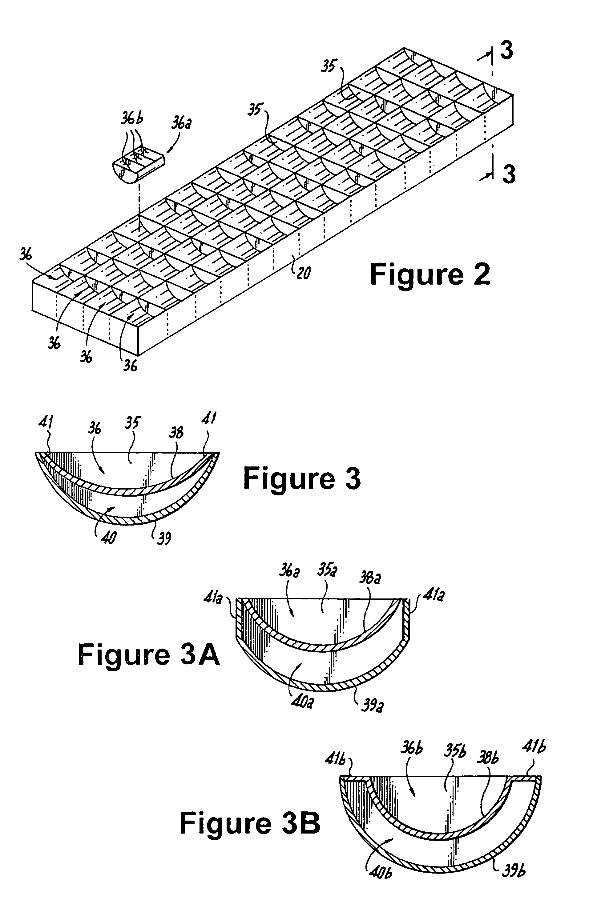
[0081]Frame 6 supports a horizontally oriented lower ice tray 21 with rotator housing 23 and a horizontally oriented upper ice tray 20 with its rotator housing 22. Control housing 10 is also attached to frame 6.

[0082]Flexible refrigerant hoses 18 connect upper tray 20 to housing 10, while corresponding hoses 19 connect to lower ice tray 21. Fixed housings for the two looped hose bundles ...


PUM


Abstract

A high throughput, short batch cycle commercial ice making machine produces salt containing, milk containing or beverage containing commercial ice, which resists melting in convenient sizes for mobile food carts, market produce, or fish displays. The machine introduces super-cooled liquid, that is in a liquid state while exposed to a temperature below freezing, into a batch of pre-formed hollow molds of one or more horizontally oriented ice forming freezing trays oriented horizontally. Using vapor compression refrigeration, the machine produces a plurality of supercooled ice segments in pockets within the freezing tray. The supercooled ice segments are rapidly subjected to a short, temporary contact with a high heat source from a sleeve integral with the freezing tray compartments, along a peripheral bottom surface of the ice segment accommodating freezing tray molds. This temporarily melts a bottom surface of each ice segment, lubricating it and loosening it. Then the machine rotates the freezing tray containing the batch of ice segments about its horizontally oriented axis to a vertically oriented dump position, thereby dumping the temporarily heated ice segments into the freezing tray. The ice cubes thus formed may be fresh water, salt water or beverage containing ice cubes.

Description

RELATED APPLICATIONS[0001]This application is based in part upon application Ser. No. 10 / 612,458 filed Jul. 2, 2003, now U.S. Pat. No. 6,920,764 which is based in part upon application Ser. No. 10 / 068,952, filed on Feb. 9, 2002, now U.S. Pat. No. 6,588,219 which claims the benefit under 35USC 119(e), of provisional patent application Ser. No. 60 / 339,885, filed on Dec. 12, 2001.FIELD OF THE INVENTION[0002]The present invention relates to making ice cubes from liquids such as milk, milk products such as yogurt, fresh water, salt water or sweetened beverage, in a horizontally oriented freezing tray having refrigerant and evaporator conduits integral with, and in intimate contact with, the ice cube mold compartments of a freezing tray, so that the resultant ice cubes have a long shelf life before melting, and wherein separation of the components of the liquid is minimized, so that the resultant ice cubes may later be melted to a liquid state where the resultant liquid has the same taste...

Claims


Application Information

Patent Timeline
IPC IPC(8): F25C1/04F25C5/10
CPCF25C1/04F25C5/10F25D2400/30F25C2400/06F25C2305/022F25C2305/0221
Inventor ZEVLAKIS, JOHN
Owner ZEVLAKIS ANASTASSIA
Why Eureka
Try Eureka